Double temperature cold water unit for air conditioning system

A technology for chillers and air conditioning systems, applied in air conditioning systems, refrigerators, irreversible cycle compressors, etc., can solve the problems of difficult construction, difficult to popularize, and low energy efficiency of units, and achieves easy popularization and popularization. Economic and social benefits, the effect of simple construction

Inactive Publication Date: 2006-01-04
TSINGHUA UNIV
View PDF0 Cites 23 Cited by
  • Summary
  • Abstract
  • Description
  • Claims
  • Application Information

AI Technical Summary

Problems solved by technology

The problem with this method is that it is difficult to popularize due to the limitation of groundwater sources.
The problem with this method is that the chiller needs to produce cold water at a low temperature of about 7°C,

Method used


Image

  • Double temperature cold water unit for air conditioning system
  • Double temperature cold water unit for air conditioning system
  • Double temperature cold water unit for air conditioning system

Examples


Example Embodiment

[0019] Example one:

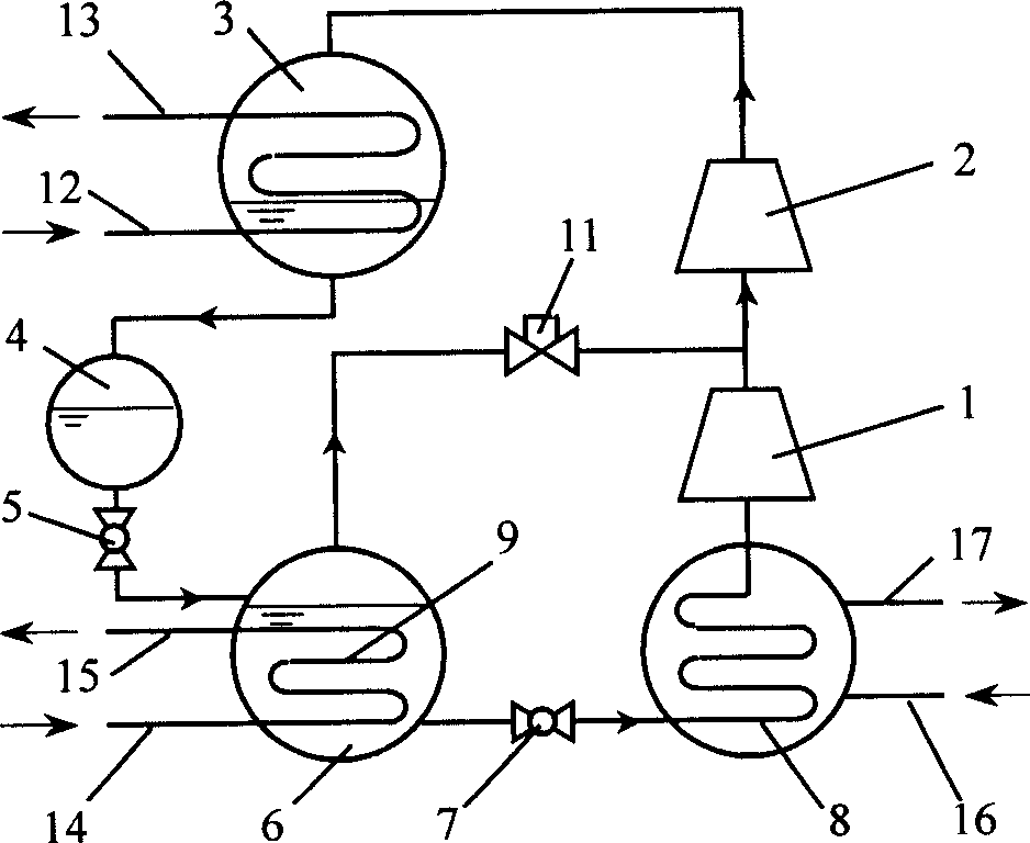
[0020] Such as figure 2 As shown, a dual-temperature chiller with independent high- and low-pressure compressors is used. The dual-temperature chiller is a two-stage compression refrigeration cycle with incomplete cooling in the middle of a two-stage throttling, a two-stage compressor composed of a low-pressure stage compressor 1 and a high-pressure stage compressor 2, a condenser 3, an accumulator 4, and a high-pressure stage The throttle valve 5, the intercooler 6, the low pressure stage throttle valve 7, the low temperature evaporator 8, the high temperature evaporator 9 and the evaporation pressure regulating valve 11 are constituted. Among them, the high-temperature evaporator 9 is a cooling coil heat exchanger, which is arranged inside the intercooler 6. When the unit is running, the high temperature evaporator 9 is immersed in the medium temperature liquid refrigerant throttled by the high pressure stage throttle valve 5, and the high temperature evap...

Example Embodiment

[0024] Embodiment two:

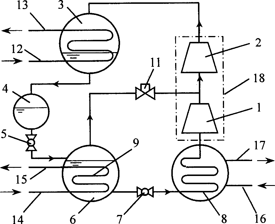
[0025] Such as image 3 As shown, in the above embodiment, the difference is that the two-stage compressor composed of the low-pressure stage compressor 1 and the high-pressure stage compressor 2 is a single-unit two-stage compressor 18, which can simplify the structure of the chiller. The outlet pipe of the evaporation pressure regulating valve 11 is connected to the connecting pipe between the discharge pipe of the low-pressure stage compressor 1 and the suction pipe of the high-pressure stage compressor 2. Others are exactly the same as the first embodiment.

Example Embodiment

[0026] Example 3:

[0027] Such as Figure 4 As shown, in the first embodiment above, the difference is that the two-stage compressor composed of the low-pressure stage compressor 1 and the high-pressure stage compressor 2 uses a centrifugal, screw, and scroll type with intermediate supplementary air. The quasi-two-stage compressor 19 with continuous compression feature can further simplify the structure of the unit. The outlet pipe of the evaporation pressure regulating valve 11 is directly connected to the intermediate air supplement port of the quasi-two-stage compressor 19. Others are exactly the same as the first embodiment.


PUM


Abstract

The present invention belongs to the field of refrigerating and air conditioning technology, and the double temperature cold water unit for air conditioning system consists of double stage compressor comprising low pressure stage compressor and high pressure stage compressor, condenser, liquid storage, high pressure stage throttle valve, middle cooler, low pressure stage throttle valve, low temperature evaporator/evaporation type air cooler, high temperature evaporator and evaporation pressure regulating valve. Structurally, the present invention features the coil heat exchanger of medium temperature cold water passage inside liquid refrigerant in the high temperature evaporator to prepare medium temperature cold water; and the preparation of low temperature cold water and cold air with the un-evaporated liquid refrigerant in the low temperature evaporator/evaporation type air cooler. The present invention can provide low temperature cold water or air at 7 deg c and medium temperature cold water at 18 deg c in high efficiency.

Description

technical field [0001] The invention belongs to the technical field of refrigeration and air-conditioning equipment, in particular to a dual-temperature chiller used in an air-conditioning system. Background technique [0002] Traditional air-conditioning systems, such as all-air systems, control indoor heat, humidity, and air quality through ventilation. The cold coil dehumidification method needs to treat the air below its dew point temperature, so a cold source with a lower temperature is required to meet the dehumidification requirements; for the indoor sensible heat load, a higher temperature cold source can meet its requirements. However, in the actual application process, since the system often uses a single cooling source to meet the indoor heat and humidity requirements at the same time, resulting in a mismatch in energy utilization and large irreversible losses in energy transfer. Moreover, the large air supply volume causes thermal comfort problems of the human b...

Claims


Application Information

Patent Timeline
IPC IPC(8): F25B1/10F24F3/06
Inventor 江亿夏建军石文星薛志峰
Owner TSINGHUA UNIV
Why Eureka
Try Eureka