Control method of mobile steel rail pneumatic welding machine and its used equipment

A control method and mobile technology, applied in welding equipment, welding equipment, arc welding equipment, etc., can solve the problems of large fluctuations in the pass rate of rail joint drop weight test, unstable welding joint quality, low degree of automation, etc. The process is stable and reliable, the effect of reducing human influence and improving the level of automation

Inactive Publication Date: 2006-01-11
攀枝花钢铁有限责任公司钢铁研究院
View PDF0 Cites 3 Cited by
  • Summary
  • Abstract
  • Description
  • Claims
  • Application Information

AI Technical Summary

Problems solved by technology

In practical application, since the welding machine does not have an automatic recording and control device, the rail welding depends entirely on the operator's experience. The degree is low and the process reproducibility is poor, resulting in large fluctuations in the qualified rate of the drop weight test of the rail joint after welding, and the quality of the welded joint is unstable

Method used


Image

  • Control method of mobile steel rail pneumatic welding machine and its used equipment
  • Control method of mobile steel rail pneumatic welding machine and its used equipment
  • Control method of mobile steel rail pneumatic welding machine and its used equipment

Examples


Embodiment 1

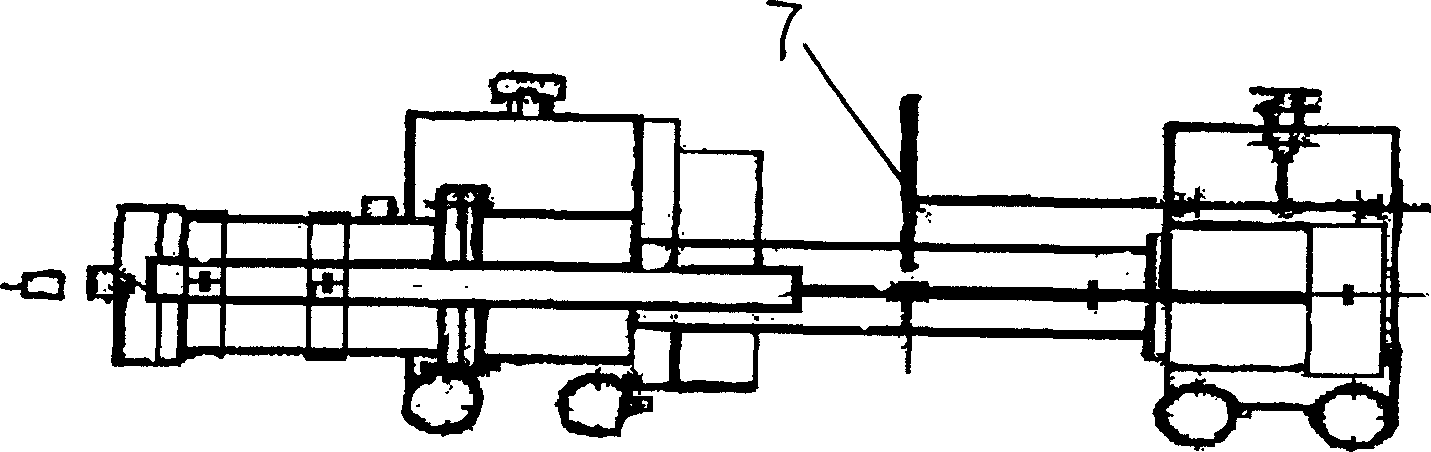
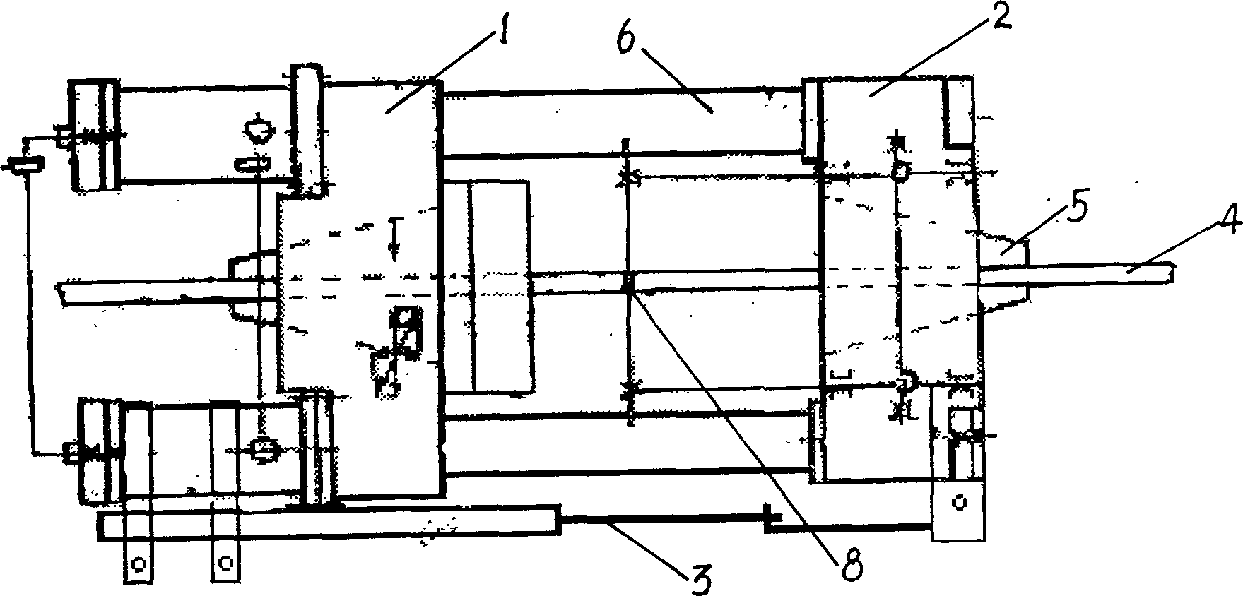
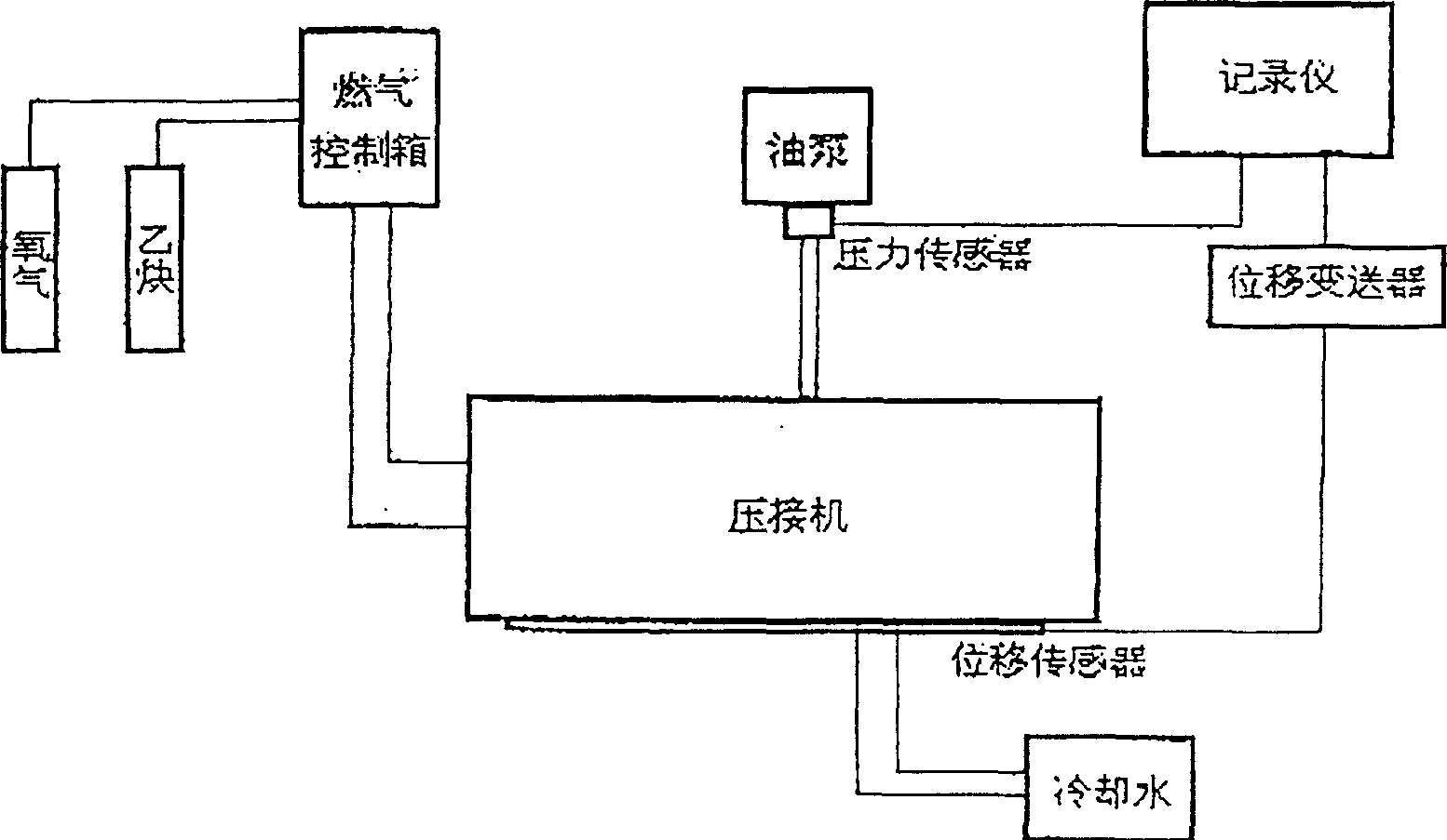
[0033] Put the two welded rails 4 that have been pretreated by end grinding and manual filing into the crimping machine, turn on the high-pressure oil pump, and adjust the weld position of the welded rails 4 and the distance between the left beam 1 and the right beam 2 of the crimping machine. distance to ensure that the tumor pushing device successfully removes the welding tumor. Tighten the rail waist slant iron 5 of the clamp waist crimping machine or tighten the compression bolts of the bottom clamping crimping machine, and tighten the rail top bolts to ensure the up and down and left and right straightness of the welded rail 4. Put in the pusher pad, close to the left beam 1 of the crimping machine, and prepare for pushing the pusher after welding. Turn on the instrument power supply, select the input signal range of the recorder, and pre-zero the recorder. Turn on the high-pressure oil pump, pre-fuel pressure to 26MPa, and adjust the initial zero position of the displac...

Embodiment 2

[0035]Put the two welded rails 4 that have been pretreated by end grinding and manual filing into the crimping machine, turn on the high-pressure oil pump, and adjust the position of the weld 8 of the welded rails 4 and the position between the left beam 1 and the right beam 2 of the crimping machine. The distance between them ensures that the tumor pushing device successfully removes the welding tumor. Tighten the rail waist slant iron of the clamp waist crimping machine or tighten the compression bolts of the bottom clamping crimping machine, and tighten the rail top bolts to ensure the up and down and left and right straightness of the welded rail 4. Put in the pusher pad, close to the left beam of the crimping machine, and prepare for the pusher after welding. Turn on the instrument power supply, select the input signal range of the recorder, and pre-zero the recorder. Turn on the high-pressure oil pump, pre-fuel pressure to 26MPa, and adjust the initial zero position of ...


PUM


Abstract

A control method for butt-welding steel rails by movable pneumatic welding machine features that the shift sensor, shift transducer and recorder are used for monitoring the relative expansive shift, compression shift and end forge shift of steel rail, the pressure sensor and recorder are used for monitoring the welding pressure and welding end forge force, and the monitored data is used to control the pressure decrement and end forge. Its apparatus is also disclosed.

Description

Technical field: [0001] The invention belongs to the technical field of railway rail air pressure welding machine control, in particular to a control method and equipment for a mobile rail air pressure welding machine. Background technique [0002] In the prior art, a general complete set of mobile rail pressure welding machine is composed of a crimping machine, a high-pressure oil pump, a heater, a tumor pushing device, a gas flow control box and a cooling water circulation system. The mobile rail air pressure welding machine is divided into the clamping waist type and the clamping rail bottom type. The crimping machine is mainly to clamp the two welded steel rails, fix their relative positions, provide the upsetting force during the heating process of the air pressure welding, and ensure the joints of the rails. End face welding and post-welding to complete the push-button requirements. This air pressure welding machine can pass TB / T2622.1-95 "Mobile Rail Air Pressure Wel...

Claims


Application Information

Patent Timeline
Patent Type & Authority Applications(China)
IPC IPC(8): B23K37/04B23K9/095
Inventor 李大东刁源生郑会军余腾义李国安林剑东
Owner 攀枝花钢铁有限责任公司钢铁研究院
Why Eureka
Try Eureka