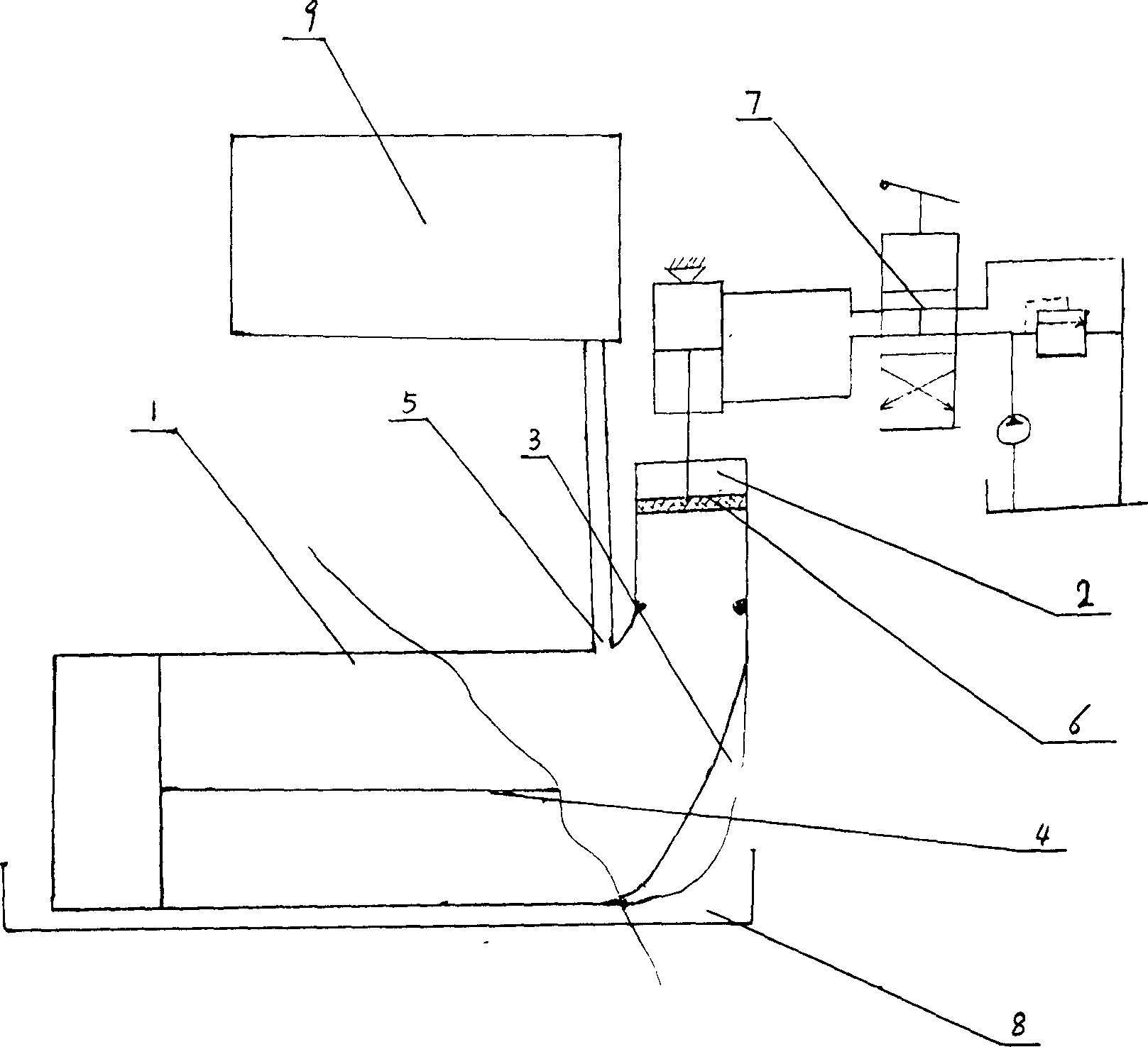
Continuous feeding discharging material sludge gas dry fermentation device and its temperature rising and maintaining method
A dry fermentation device, biogas technology, applied in waste fuel, gas production bioreactor, etc., can solve the problems of difficulty in discharging, limitation, easy damage to cement pool and air leakage, etc., and achieves the effect of simple structure and remarkable thermal insulation effect.
- Summary
- Abstract
- Description
- Claims
- Application Information
AI Technical Summary
Problems solved by technology
Method used
Image
Examples
Embodiment 1
[0023] First dig a deep pit on the ground, the length, width and depth of the pit are 2 meters away from the periphery of the dry fermentation device as an isolation layer, and the bottom of the dry fermentation device is placed on a base 0.5 meters away from the bottom of the pit to cut off the influence of the ground temperature on the fermentation device; Insert a foam plastic board at a depth of 1 meter from the four walls and the bottom of the pit, and the thickness of the board is 10 cm, to further isolate the influence of ground temperature; Warm heat storage, the walls and bottom of the pit are built with bricks, the cement surface is hung, and asphalt is coated on the outside to enhance heat absorption and increase temperature; after that, a solar greenhouse collector is added on the pit; dry fermentation in autumn and winter The device is 2 meters away from the wall of the pit, 1 meter above, and 0.5 meters at the bottom. Fill in the 3 cm straw for compaction. : The ...
Embodiment 2
[0025] First dig a deep pit on the ground. The length, width and depth of the pit are 2.5 meters away from the periphery of the dry fermentation device as an isolation layer. The bottom of the dry fermentation device is placed on a base 0.5 meters away from the bottom of the pit to cut off the influence of ground temperature on the fermentation device; Insert a foam plastic board at a depth of 1 meter from the four walls and the bottom of the pit, and the thickness of the board is 10 cm, to further isolate the influence of ground temperature; Warm heat storage, the walls and bottom of the pit are built with bricks, the cement surface is hung, and asphalt is coated on the outside to enhance heat absorption and increase temperature; after that, a solar greenhouse collector is added on the pit; dry fermentation in autumn and winter The device is 2.5 meters away from the pit wall, 1.2 meters on the top, and 0.5 meters on the bottom. Fill the isolation layer with 3.5 cm straw for co...
Embodiment 3
[0027] First dig a deep pit on the ground, the length, width and depth of the pit are 2.8 meters away from the periphery of the dry fermentation device as an isolation layer, and the bottom of the dry fermentation device is placed on a base 0.5 meters away from the bottom of the pit to cut off the influence of the ground temperature on the fermentation device; Insert a foam plastic board at a depth of 1 meter from the four walls and the bottom of the pit, and the thickness of the board is 10 cm, to further isolate the influence of ground temperature; Warm heat storage, the walls and bottom of the pit are built with bricks, the cement surface is hung, and asphalt is coated on the outside to enhance heat absorption and increase temperature; after that, a solar greenhouse collector is added on the pit; dry fermentation in autumn and winter The device is 3 meters away from the wall of the pit, 1.5 meters above, and 0.5 meters at the bottom. Fill the isolation layer with 4 centimete...
PUM
 Abstract
Description
Claims
Application Information
 - R&D
- Intellectual Property
- Life Sciences
- Materials
- Tech Scout
- Unparalleled Data Quality
- Higher Quality Content
- 60% Fewer Hallucinations
Browse by: Latest US Patents, China's latest patents, Technical Efficacy Thesaurus, Application Domain, Technology Topic, Popular Technical Reports.
© 2025 PatSnap. All rights reserved.Legal|Privacy policy|Modern Slavery Act Transparency Statement|Sitemap|About US| Contact US: help@patsnap.com

