Concrete core cement soil stirring pile machine and its construction technological method

A technology of cement-soil mixing piles and concrete cores, applied in the direction of sheet pile walls, foundation structure engineering, construction, etc.

Inactive Publication Date: 2006-01-11
NANJING UNIV
View PDF0 Cites 23 Cited by
  • Summary
  • Abstract
  • Description
  • Claims
  • Application Information

AI Technical Summary

Problems solved by technology

[0006] The purpose of the present invention is to overcome the problems existing in the existing concrete-core cement-soil mixing pile machine, and provide a special pile machine for constructing concrete-core cement-soil mixing pile and its construction method

Method used


Image

  • Concrete core cement soil stirring pile machine and its construction technological method
  • Concrete core cement soil stirring pile machine and its construction technological method
  • Concrete core cement soil stirring pile machine and its construction technological method

Examples


Embodiment Construction

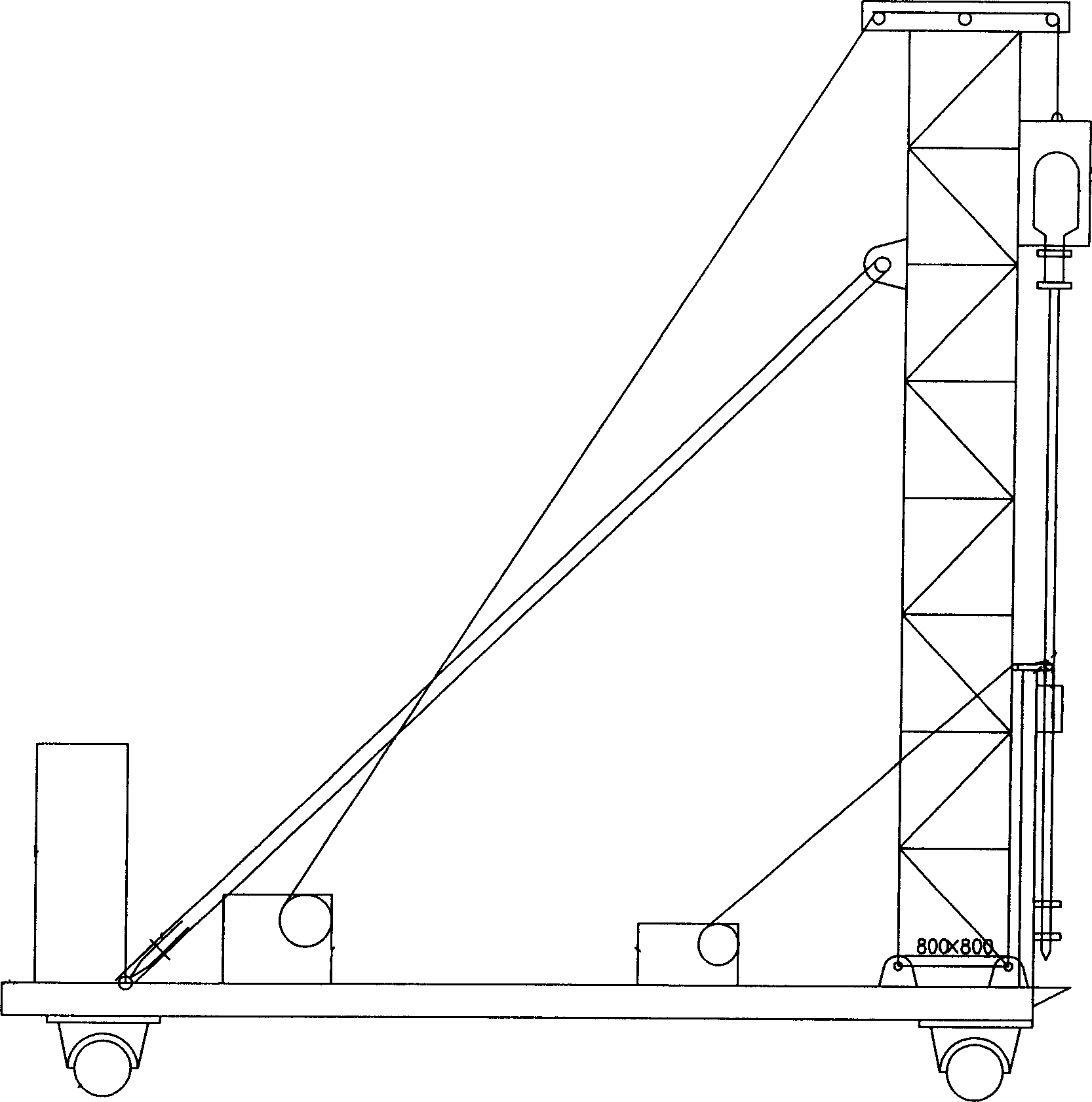
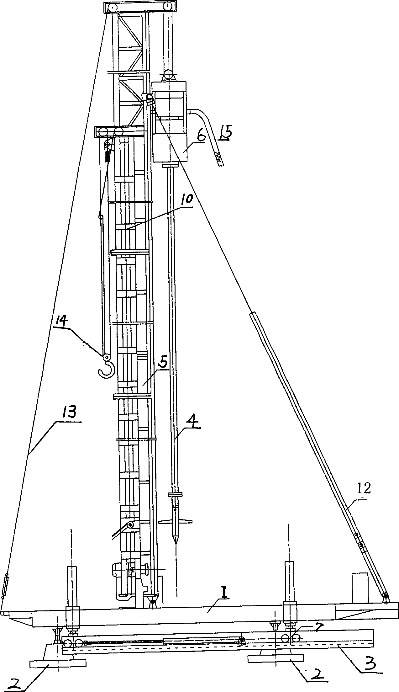
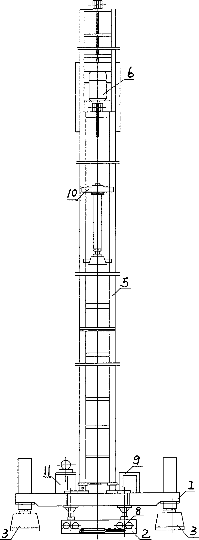
[0020] refer to Figure 2-A and Figure 2-B Can basically see the whole picture of the present invention-concrete core cement-soil mixing pile machine. The bottom of the pile driver is a hydraulic walking system, including a hydraulic pump station (11), a base and a leg beam (1), a traverse beam (2), a longitudinal beam (3), a longitudinal roller bracket (7) and a horizontal roller The bracket (8), the base and the outrigger beam (1) rest on the vertical and horizontal brackets (7, 8), and the roller brackets (7, 8) are respectively placed on the vertical moving beam (3) and the horizontal moving beam (2) Above, the hydraulic pump station (11) is fixed on the base and the support beam (1), and controls the longitudinal and lateral movement of the base; the frame (5) is welded on the slideable guide rail in the center of the base (1), and the guide rail can The guide groove slides, so that after the construction of the deep cement-soil mixing pile is completed, the central ax...


PUM


Abstract

The present invention discloses a concrete core cement earth stirring pile machine and its construction process and method. The bottom portion of said pile machine is equipped with hydraulic walking system, including machine frame, base seat, hydraulic pump station, longitudinal and transverse moving beams, longitudinal and transverse roller supporting frames, guideway, deep stirring machine head, drilling machine, drill bit, slurry pump, distribution box and hydraulic pile-pressing system.

Description

1. Technical field [0001] The invention relates to a construction machine for building foundation engineering—a pile driver and its construction technology, in particular to a special pile driver for a concrete-cored cement-soil mixing pile and its construction technology. 2. Background technology [0002] The concrete core cement-soil mixing pile is a composite pile formed by inserting a prefabricated reinforced concrete small square pile into the cement-soil mixing pile in time. In the mid-1990s, with the application of concrete-core cement-soil mixing piles, a cement-soil mixing pile machine with a diesel hammer was produced, that is, the first generation of concrete-core cement-soil mixing pile machines. A diesel hammer is added to the foundation of the pile driver, from figure 1 It can be seen that the frame of the pile driver rests on two moving horizontal tubes, and the displacement of the pile driver depends on the pulling of the main winch controlled by the distrib...

Claims


Application Information

Patent Timeline
Patent Type & Authority Applications(China)
IPC IPC(8): E02D5/34E02D5/50E02D7/00
Inventor 董平胡安兵张健康易敏陈景雅高建新曹建周明
Owner NANJING UNIV
Why Eureka
Try Eureka