Control valve for a device to modify the timing of an internal combustion engine

A technology for controlling time and controlling valves, which is applied in the direction of valve operation/release devices, valve devices, fluid pressure actuators, etc., to achieve the effect of increasing the filtration area

Inactive Publication Date: 2006-01-25
SCHAEFFLER TECH AG & CO KG
View PDF1 Cites 22 Cited by
  • Summary
  • Abstract
  • Description
  • Claims
  • Application Information

AI Technical Summary

Problems solved by technology

This has the consequence that contaminated particles can r

Method used


Image

  • Control valve for a device to modify the timing of an internal combustion engine
  • Control valve for a device to modify the timing of an internal combustion engine
  • Control valve for a device to modify the timing of an internal combustion engine

Examples


Embodiment Construction

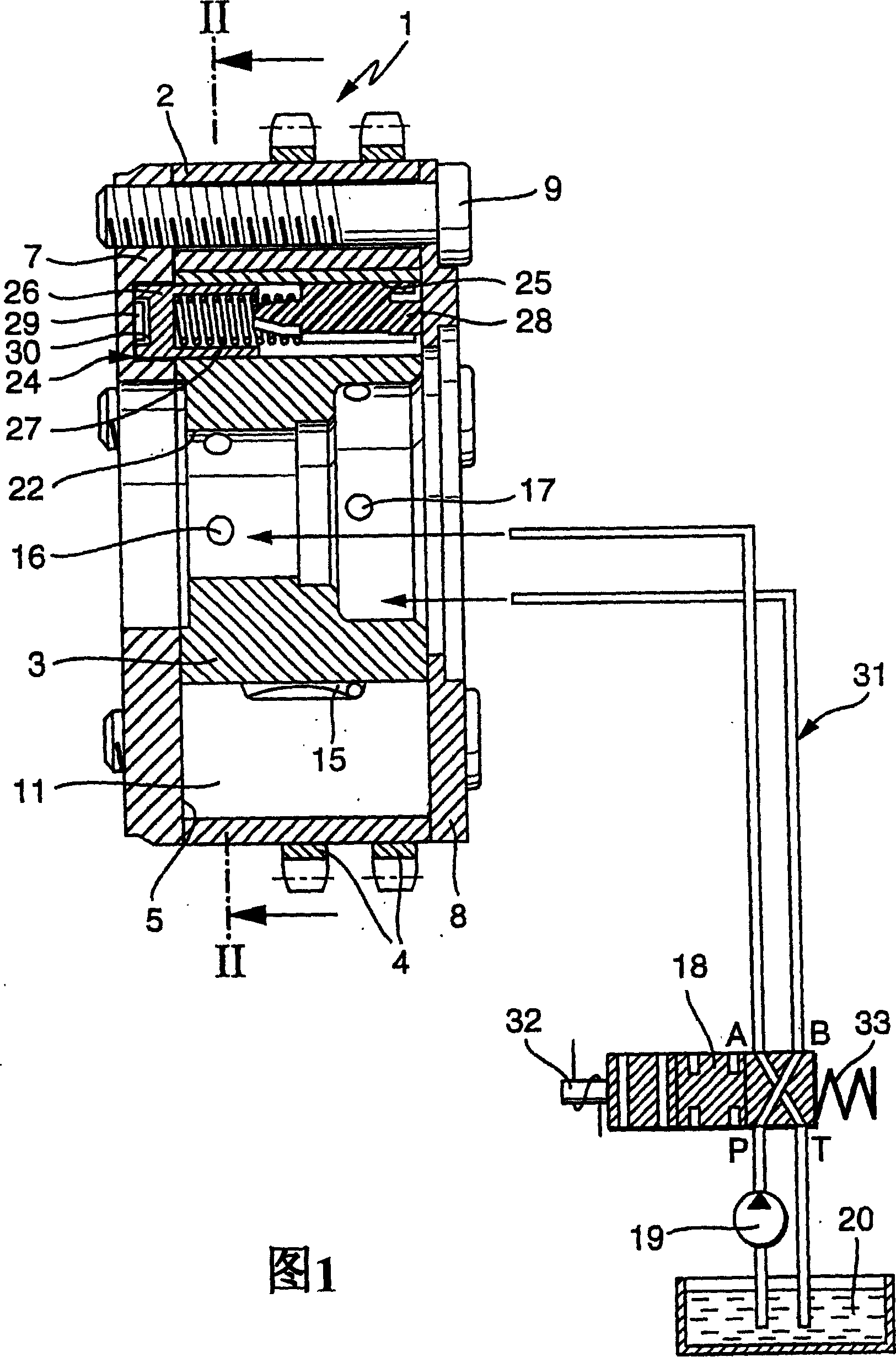
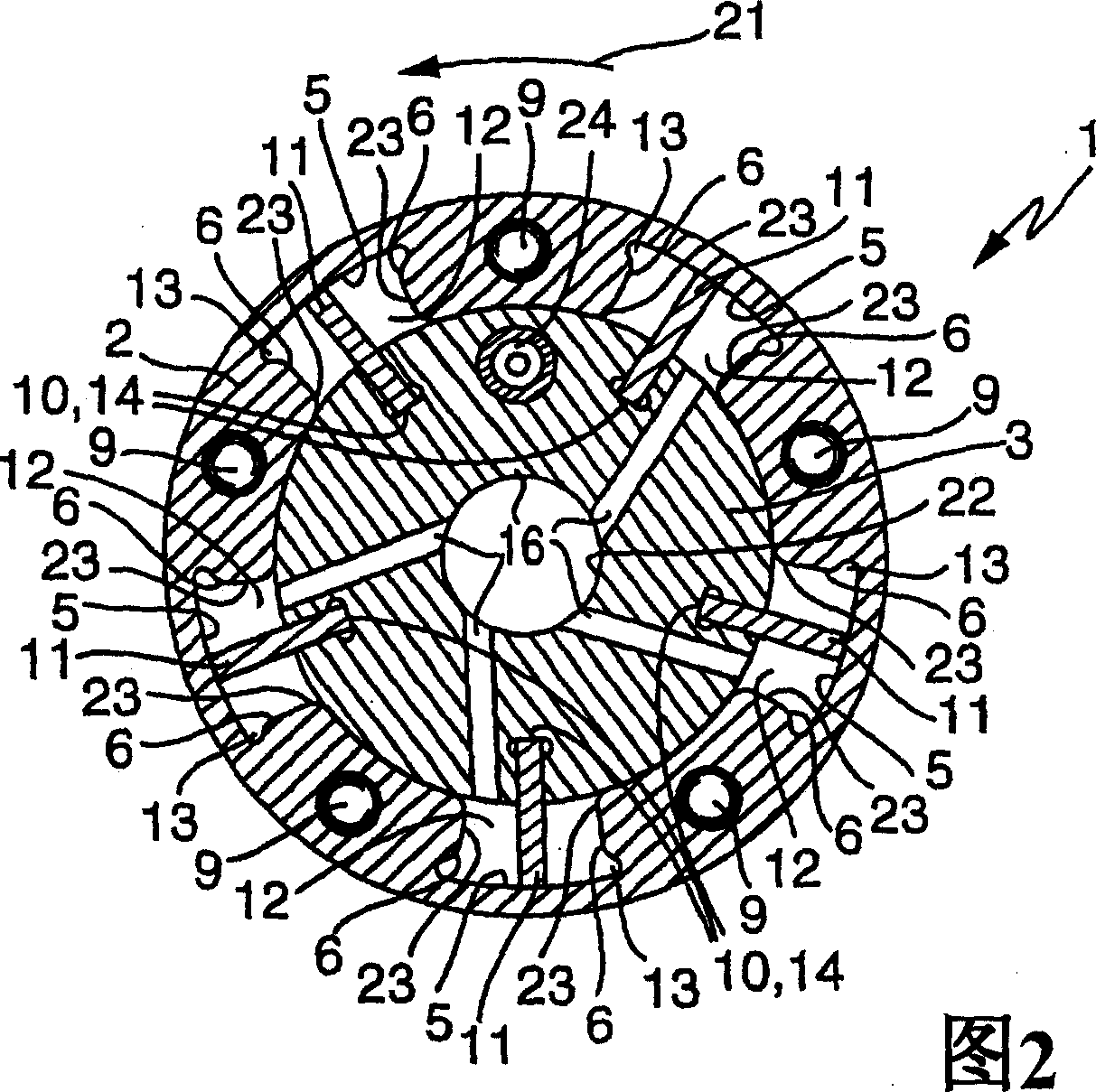
[0039] 1 and 2 show a device 1 for varying the control timing of an internal combustion engine. The device 1 basically consists of a stator 2 and a rotor 3 arranged concentrically therewith. The drive wheel 4 is connected to the stator 2 in a rotationally fixed manner and is designed as a sprocket in the illustrated embodiment. Likewise the embodiment of the transmission wheel 4 can be a belt or a gear. The stator 2 is rotatably mounted on the rotor 3 , wherein in the illustrated embodiment the inner peripheral surface of the stator 2 is provided with five gaps 5 spaced from one another in the circumferential direction. The gap 5 is limited in the radial direction by the stator 2 and the rotor 3 , in the circumferential direction by the two side walls 6 of the stator 2 and in the axial direction by the first side cover 7 and the second side cover 8 . Each gap 5 is hermetically closed in this way. The first side cover 7 and the second side cover 8 are connected to the stator...


PUM


Abstract

The invention relates to a control valve (18) of a device (1) for varying the control time of an internal combustion engine. In this case, a targeted rotation of the camshaft relative to the crankshaft can be achieved by means of a hydraulic actuator. A control valve (18) with a working connection (A, B), a pressure oil connection (P) and at least one tank connection (T, T1, T2) controls the pressure oil supply or pressure oil discharge of the hydraulic actuator. The invention proposes to arrange a filter (46) between the pressure oil connection (P) and the working connections (A, B).

Description

technical field [0001] The invention relates to a control valve for a device for varying the control time of an internal combustion engine, which has a substantially hollow cylindrical valve housing, an axially displaceable control piston arranged inside the valve housing, a pressure oil connection, two A working connection and at least one tank connection, wherein the working connection can be connected to the pressure oil connection and the tank connection via the axial displacement of the control piston in the valve housing, and a filter. Background technique [0002] Camshafts are used in internal combustion engines to control the gas exchange valves. The camshaft is installed in the internal combustion engine in such a way that the cams mounted on the camshaft are located next to cam attachments, such as barrel tappets, rocker arms or swing arms. If the camshaft turns, the cam on the cam attachment is selected, which re-controls the gas exchange valve. The position an...

Claims


Application Information

Patent Timeline
IPC IPC(8): F01L1/344
CPCY10T137/86614F01L1/3442F01L1/022Y10T137/86622F01L2001/3443F01L2001/34469F16K11/0716F01L1/026F15B21/041F15B13/0402F16K31/363F16K31/1226F16K31/3835F01L2001/3444F01L1/024
Inventor 安德烈亚斯·斯特劳布安德烈亚斯·罗尔延斯·霍庇
Owner SCHAEFFLER TECH AG & CO KG
Why Eureka
Try Eureka