
Fluorescence detection optical device with microflow control chip

A microfluidic chip and fluorescence detection technology, applied in the field of fluorescence detection of microfluidic chips, can solve the problems of inability to adjust the working distance of the objective lens group, limit the selection of fluorescent dyes, take a long time, etc., and achieve a wide range of wavelengths, Overcome the influence of human factors and improve the effect of flexibility

Inactive Publication Date: 2006-01-25
DONGHUA UNIV
View PDF0 Cites 27 Cited by
  • Summary
  • Abstract
  • Description
  • Claims
  • Application Information

AI Technical Summary

Problems solved by technology

In order to adapt to different types of chips, the micropipe positioning of the existing microfluidic chip fluorescence detector adopts a manual method, and the chip is moved manually, which requires the operator to have certain experience and takes a long time;
[0006] (2) The laser wavelength used for excitation light is fixed at one wavelength and cannot be freely replaced, which limits the choice of fluorescent dyes;
[0007] (3) The position of the objective lens group in the optical path system is fixed, and the working distance of the objective lens group cannot be adjusted according to the wavelength of the excitation light, which limits the sensitivity of the detection;
[0008] (4) The size of the aperture is fixed, and the size of the aperture cannot be adjusted according to the needs, which limits the sensitivity of the detection

Method used


Image

  • Fluorescence detection optical device with microflow control chip
  • Fluorescence detection optical device with microflow control chip
  • Fluorescence detection optical device with microflow control chip

Examples


Embodiment Construction

[0041] The present invention will be further described below in conjunction with the embodiments and accompanying drawings, but the protection scope of the present invention should not be limited thereby.

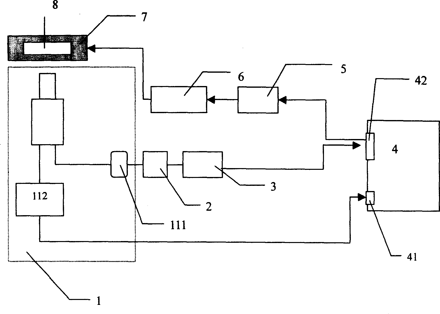
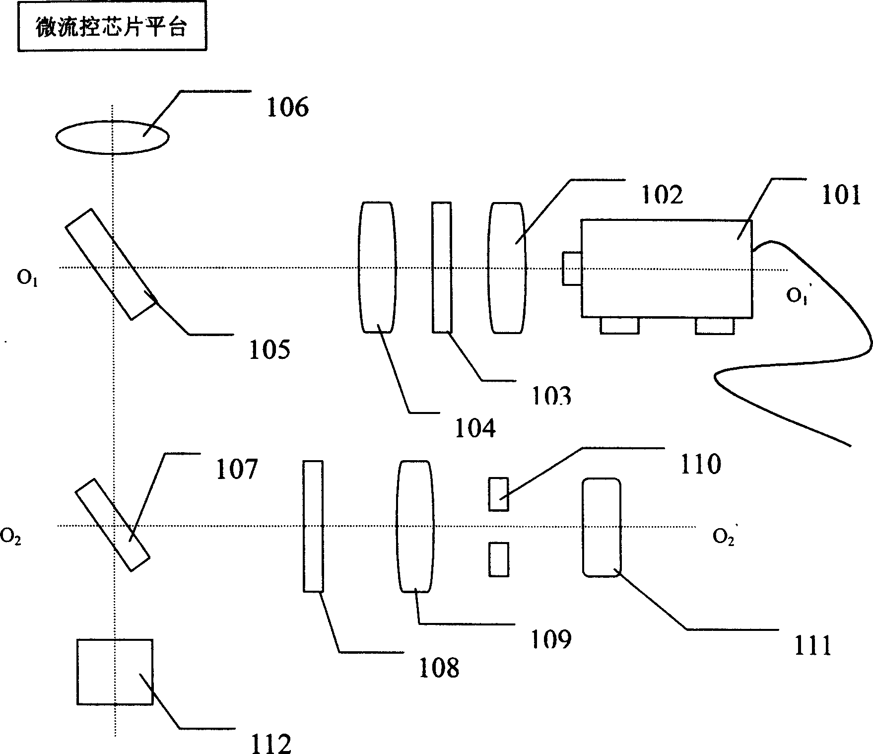
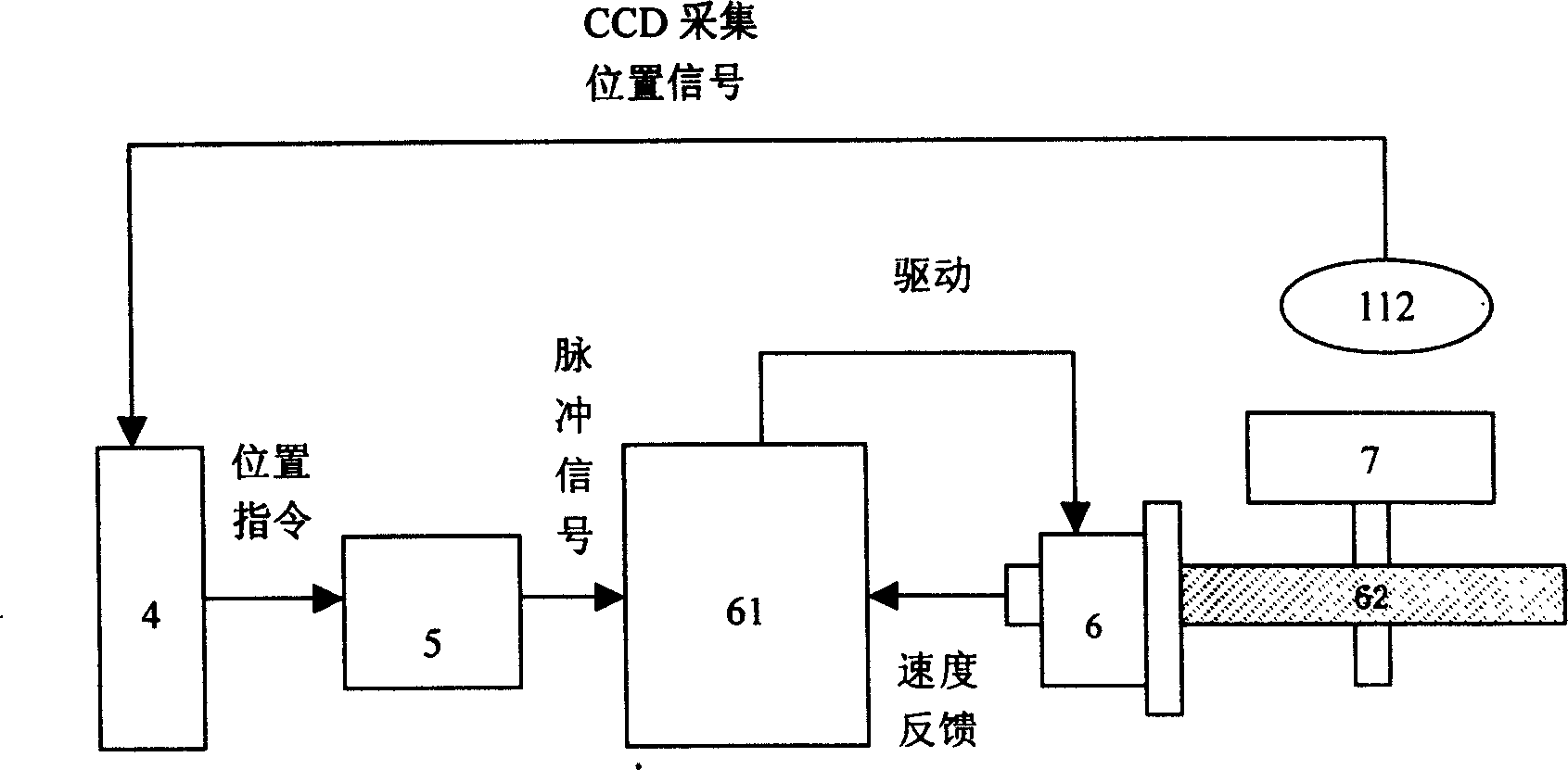
[0042] see first figure 1 and figure 2 , the present invention is a microfluidic chip fluorescence detection optical device, its composition includes:

[0043] ① Detection optical path 1: along the forward direction of the light beam emitted by the light source 101, the same as the optical axis O 1 o 1 'The first lens group 102, the first optical filter 103, the second lens group 104, the half-mirror 105 are followed by the first lens group 102, the half-mirror 105 is placed at 45° with the above-mentioned light beam, and the half-mirror The reflected light beam direction of the mirror 105 is the objective lens group 106 and the chip platform 7 for placing the microfluidic chip 8, and the light beam reflected by the microfluidic chip 8 passes through the half mirror 105...


PUM


Abstract

The invention is a micro-flow control chip fluorescent detection optical device, comprising light source, filter plate, semitransparent semi-reflector, object lens group and photoelectric multiplier tube, and the structure of the detection optical device includes detecting light path, information collection interface and control interface. The invention is wide-application range, and flexible to adjust, the object lens group and the micro-channel of the micro-flow control chip automatically focus and the data processing is automatically completed by computer, quick and high-accuracy.

Description

technical field [0001] The invention relates to fluorescence detection of a microfluidic chip, in particular to an optical device for fluorescence detection of a microfluidic chip with an auto-focus function. Background technique [0002] At present, microfluidic chips are widely used in various fields, including medical diagnosis, environmental protection, drug screening, gene sequencing, etc., for high-speed and efficient separation or processing of biological macromolecules such as DNA, peptides, and proteins. Fluorescence detection is one of the important means to determine the composition and content of related components after the microfluidic chip has been systematically processed. [0003] The basic principle of the existing microfluidic chip fluorescence detection optical device is: the laser light generated by the laser passes through a filter to become approximately monochromatic light; the monochromatic light is irradiated into the micropipe of the chip through t...

Claims


Application Information

Patent Timeline
IPC IPC(8): G01N21/64
Inventor 丁永生李汪根
Owner DONGHUA UNIV
Learn More