
Non-aqueous electrolyte battery

A non-aqueous electrolyte and battery technology, used in non-aqueous electrolyte batteries, electrolyte battery manufacturing, lithium batteries, etc., can solve problems such as difficulty in fully improving safety, and achieve the effect of improving overcharge characteristics and suppressing internal short circuits

Inactive Publication Date: 2006-01-25
SANYO ELECTRIC CO LTD
View PDF3 Cites 7 Cited by
  • Summary
  • Abstract
  • Description
  • Claims
  • Application Information

AI Technical Summary

Problems solved by technology

[0013] In the case of lithium-nickel-cobalt composite oxide, a large amount of lithium escaped from the crystal during overcharge exists in the crystal, and this lithium is deposited on the negative electrode and can become a heat source, so it is difficult to sufficiently improve overcharge. security

Method used


Image

  • Non-aqueous electrolyte battery
  • Non-aqueous electrolyte battery
  • Non-aqueous electrolyte battery

Examples


Embodiment

[0076] [preliminary test]

[0077] The above-mentioned electron beam cross-linked separators (used in batteries A1, A3, B1, and C1 of the present invention described later and comparative batteries X4, Y3, and Z3) and heat-resistant layer-laminated separators (used in batteries of the present invention described later) were studied. A2, A4 and comparative battery X5), the cut-off temperature (hereinafter sometimes referred to as SD temperature) and membrane rupture temperature (hereinafter sometimes referred to as is the MD temperature), and the results are shown in Table 1. In addition, the production method of the evaluation battery, the evaluation device, and the measurement method of SD temperature and MD temperature are as follows.

[0078] [How to make an evaluation battery (cell)]

[0079] Such as Figure 5 As shown, two cell sheets 14 were prepared in which a substantially square aluminum foil (thickness: 15 μm) 12 was arranged on one surface of a glass substrate 11...

Embodiment 1

[0092] As Example 1, the battery shown in the best mode for carrying out the above invention was used.

[0093] The thus fabricated battery is hereinafter referred to as the inventive battery A1.

Embodiment 2

[0095] A battery was produced in the same manner as in Example 1 above except that a heat-resistant layer-laminated separator was used instead of an electron beam-crosslinked separator as the separator.

[0096] The battery thus fabricated is hereinafter referred to as the inventive battery A2.

[0097] Here, the heat-resistant layer-laminated separator was produced by the method shown below.

[0098] First, polyamide (PA), which is a water-insoluble heat-resistant material, is dissolved in a solution of N-methyl-2-pyrrolidone (NMP) as a water-soluble solvent, and polycondensation is performed at a low temperature in the solution to produce polyamide-doped liquid. Next, the dopant solution is applied to one side of a polyethylene (PE) microporous membrane as a base material to a predetermined thickness, then immersed in water to remove the water-soluble NMP solvent, and at the same time carry out water-insoluble Precipitation / coagulation of polyamides. Thus, a microporous p...


PUM

PropertyMeasurementUnit
melting pointaaaaaaaaaa
thicknessaaaaaaaaaa

Abstract

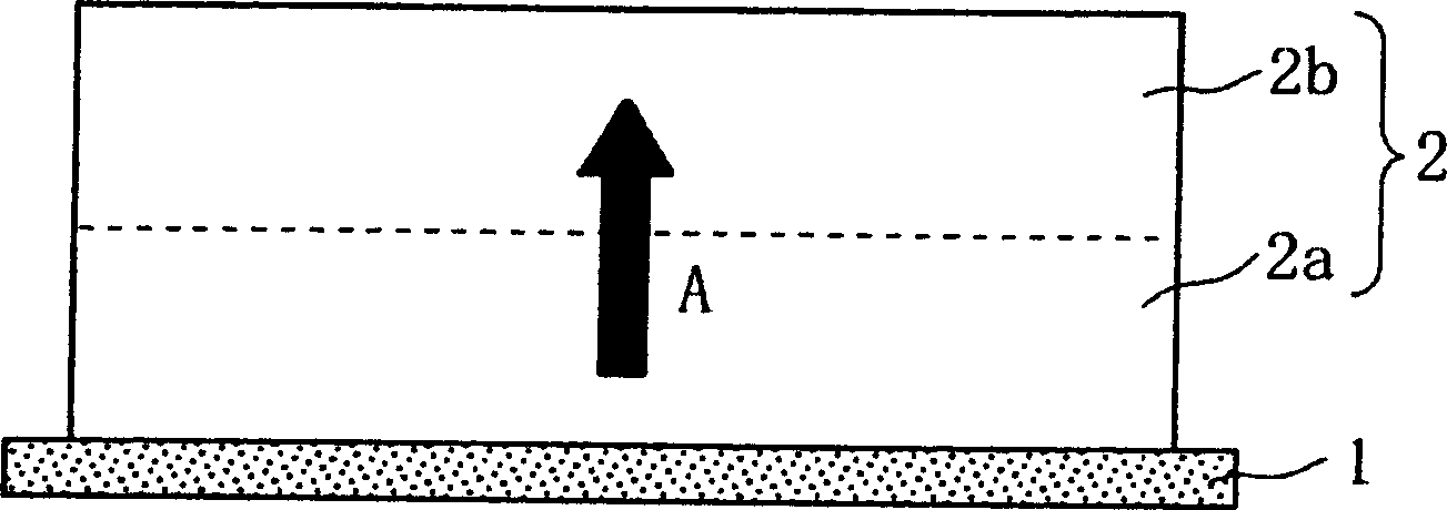
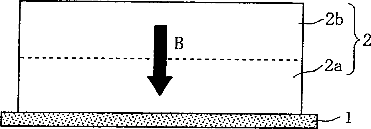
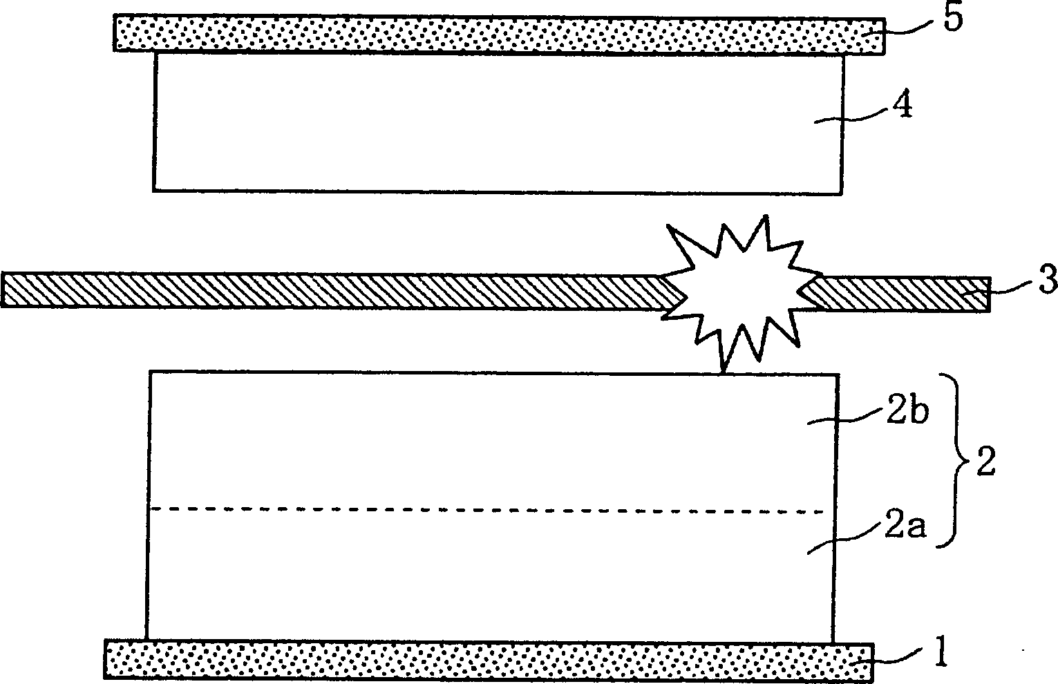
The present invention provides a positive electrode including a positive electrode active material-layer ( 2 ) containing a plurality of positive electrode active materials and being formed on a surface of a positive electrode current collector ( 1 ), a negative electrode including a negative electrode active material layer ( 4 ), and a separator ( 3 ) interposed between the electrodes. The positive electrode active material-layer ( 2 ) is composed of two layers ( 2 a) and ( 2 b) having different positive electrode active materials, and of the two layers ( 2 a) and ( 2 b), the layer ( 2 b) that is an outer layer contains as its main active material a positive electrode active material having the highest thermal stability among the positive electrode active materials. The meltdown temperature of the separator ( 3 ) is 180 DEG C. or higher. Thus, the non-aqueous electrolyte battery that is capable of improving safety, particularly tolerance of the battery for overcharging.

Description

technical field [0001] The present invention relates to improvement of nonaqueous electrolyte batteries such as lithium ion batteries and polymer batteries, and particularly relates to nonaqueous electrolyte batteries excellent in safety during overcharge. Background technique [0002] In recent years, the miniaturization and weight reduction of mobile information terminals such as mobile phones, notebook computers, and PDAs has rapidly progressed, and batteries serving as driving power sources have been required to have higher capacities. Non-aqueous electrolyte batteries, which are charged and discharged by moving lithium ions between the positive and negative electrodes along with charging and discharging, have high energy density and high capacity, so they are widely used as driving power sources for mobile information terminals as described above. use. In addition, its characteristics have recently been used not only for mobile devices such as mobile phones, but also f...

Claims


Application Information

Patent Timeline
Patent Type & Authority Applications(China)
IPC IPC(8): H01M10/40H01M10/00H01M4/02H01M4/58H01M4/48H01M4/131H01M4/36H01M10/05H01M10/052H01M50/414H01M50/417H01M50/423H01M50/449H01M50/489H01M50/491
CPCH01M4/133H01M4/505H01M2/1686H01M4/525H01M4/1391H01M10/0525H01M10/0565H01M2/1653H01M10/0587H01M10/4235H01M4/5825Y02E60/122H01M2004/028H01M4/131H01M4/366Y02E60/10H01M50/449H01M50/417H01M50/414H01M50/491H01M50/489H01M50/423H01M10/058H01M50/403
Inventor 井町直希高野靖男吉村精司藤谷伸
Owner SANYO ELECTRIC CO LTD
Learn More