Bearing apparatus for a driving wheel of vehicle

A bearing device and vehicle drive technology, applied in rotating bearings, rolling contact bearings, bearings, etc., can solve problems such as stick-slip noise, and achieve the effect of improving life and preventing stick-slip noise and friction and wear.

Inactive Publication Date: 2006-02-01
NTN CORP
View PDF1 Cites 2 Cited by
  • Summary
  • Abstract
  • Description
  • Claims
  • Application Information

AI Technical Summary

Problems solved by technology

This results in repeated relative rotation between the caulked portion 51c and the shoulder 60 over a long period of time, thus producing not only a stick-slip noise but also a rattle noise (rattle) due to the continuation of the frictional wear.

Method used


Image

  • Bearing apparatus for a driving wheel of vehicle
  • Bearing apparatus for a driving wheel of vehicle
  • Bearing apparatus for a driving wheel of vehicle

Examples


Embodiment 1

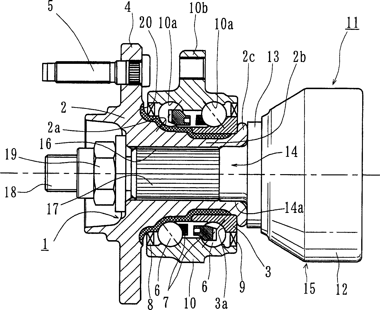
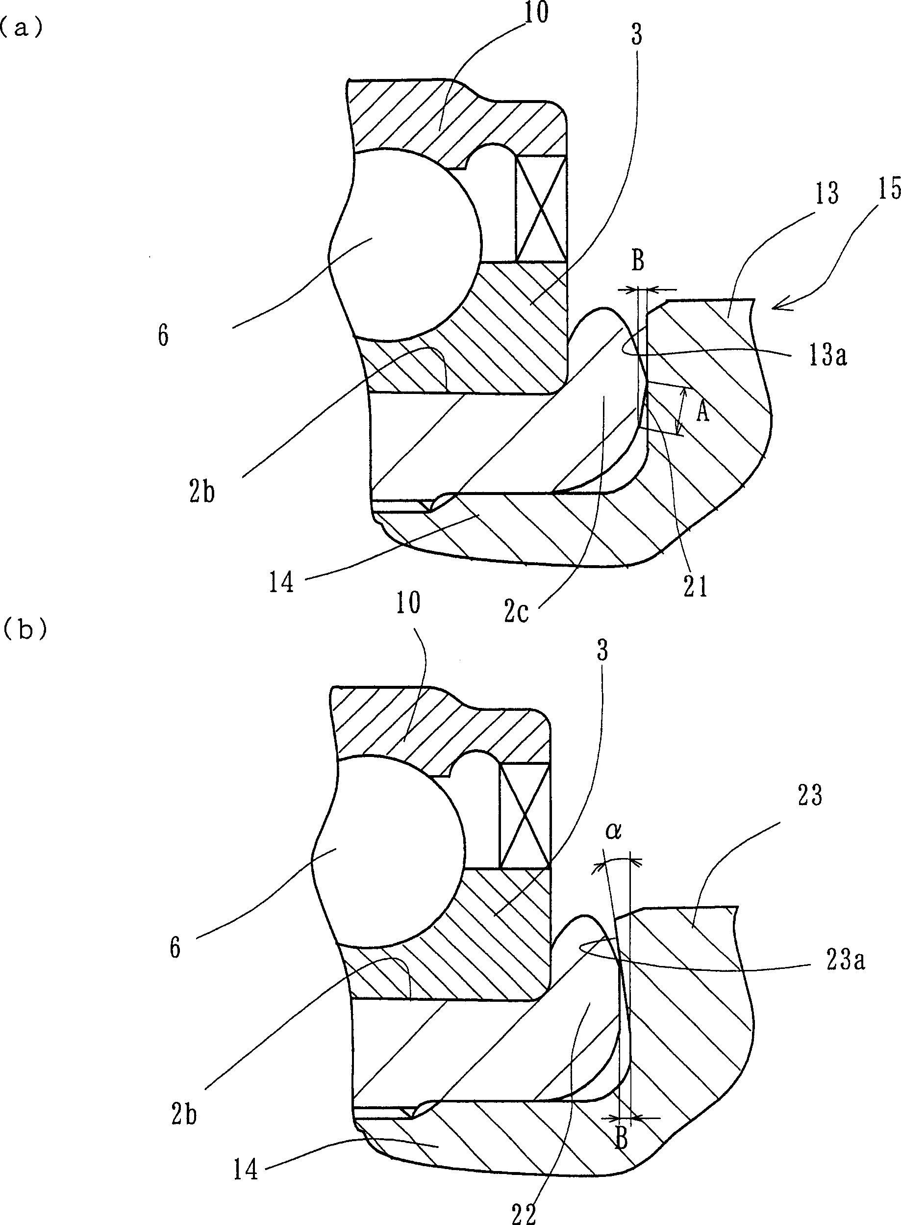
[0029] figure 1 Representing a first embodiment of a bearing device for a drive wheel of a vehicle of the present invention, figure 2 (a) is figure 1 A zoomed-in view of a portion of the , while figure 2 (b) is figure 2 Magnified view of a modification of (a). In the following description, the term "outside" of the device (left-hand side in the figure) refers to the side that is located outside the vehicle body when the bearing device is installed on the vehicle body, while the term "inside" of the device (the Right-hand side) refers to the side located inside the vehicle body when the bearing unit is installed on the vehicle body.

[0030] A bearing device for a drive wheel of a vehicle includes an inner part 1 , an outer part 10 , and a double row of rolling elements (balls) 6 rotatably accommodated between the inner part 1 and the outer part 10 . The inner part 1 comprises a hub 2 and a separate inner ring 3 press-fitted on the hub 2 . The wheel hub 2 has a wheel m...

Embodiment 2

[0042] Figure 4 is a longitudinal sectional view of a second embodiment of the bearing device for a driving wheel of a vehicle of the present invention. Figure 5 yes Figure 4 A magnified view of a portion of . The same reference numerals are used to denote the same components having the same functions as those of the first embodiment.

[0043] This bearing arrangement is the so-called "third generation" and it comprises a hub wheel 24, a double row rolling bearing 25, and a constant velocity universal joint 26, while the double row rolling bearing 25 comprises an outer part 10, an inner part 27, and a double row Rolling elements 6 and 6.

[0044] The inner part 27 includes a wheel hub 24 and the inner ring 3 press-fitted on the wheel hub 24 . The wheel hub 24 is made of medium carbon steel (for example, S53C) containing 0.40% to 0.80% carbon by weight, and has an inner raceway surface 24a formed on its inner peripheral surface, and Axially extending cylindrical portion...


PUM


Abstract

The present invention provides a bearing apparatus for a vehicle driving wheel which prevents generation of stick-slip noise as well as fretting wear to improve durability of the bearing apparatus has an outer member ( 10 ) formed with double row outer raceway surfaces ( 10 a , 10 a) on its inner circumferential surface. An inner member ( 1, 27 ) is formed with double row inner raceway surface ( 2 a ( 24 a), 3 a) opposite to the double row outer raceway surfaces ( 10 a , 10 a). Double row rolling elements ( 6 ) are freely rollably maintained between the outer and inner raceway surfaces ( 10 a , 10 a ; 2 a ( 24 a), 3 a), respectively, of the outer and inner member ( 10; 1, 27 ). A constant velocity universal joint ( 11, 26 ), for torque transmission, is inserted into the inner member ( 10; 1, 27 ). The constant velocity universal joint abuts and is axially separably connected to the inner member via a nut ( 19 ). The end surface ( 13 a , 23 a , 28 a) of a shoulder ( 13, 28 ) of an outer joint member ( 15, 29 ) and an end surface of the inner member ( 1, 27 ) are previously formed so that these end surfaces line contact with each other at a vertex formed by inclined surfaces on the end of the inner member ( 1,27 ).

Description

technical field [0001] The present invention relates to a bearing device for supporting a drive wheel of a vehicle such as an automobile, and more particularly to a bearing device for a drive wheel of a vehicle for rotatably supporting the drive wheel (i.e. , the front wheels of a front front drive vehicle, the rear wheels of a front rear drive or rear rear drive vehicle, and the front and rear wheels of a four-wheel drive vehicle). Background technique [0002] The power transmission device of the vehicle not only needs to transmit power from the engine to the vehicle, but also needs to allow the radial and axial displacement or momentum displacement (momentum displacement) of the wheels caused by the beating of the vehicle when the vehicle is running on an uneven road or during turning of the vehicle. ). Therefore, one end of the drive shaft arranged between the engine and the drive wheels is connected to the differential gear unit through a sliding type constant velocity...

Claims


Application Information

Patent Timeline
Patent Type & Authority Applications(China)
IPC IPC(8): F16C19/18B60B35/18
CPCB60B27/0094F16C43/04B60B27/0005B60B27/0084F16D3/223B60B27/0026F16C19/186F16D2003/22326F16C19/527F16C33/586F16C2326/02F16D2001/103
Inventor 寺田博纪田洼孝康有竹恭大
Owner NTN CORP
Why Eureka
Try Eureka