
Bolometric detector, infrared detection device employing such a bolometric detector and process for fabricating this detector

A detector and radiant heat technology, applied in the direction of electric radiation detectors, radiation control devices, electric solid devices, etc., can solve the problems of low resistivity, complex products, etc., and achieve the effect of optimizing performance and increasing quantity

Inactive Publication Date: 2006-02-01
ULIS SAS
View PDF4 Cites 5 Cited by
  • Summary
  • Abstract
  • Description
  • Claims
  • Application Information

AI Technical Summary

Problems solved by technology

Therefore, this will make the product very complex
In addition, having to separate the electrodes further limits the use of low-resistivity heat-radiating materials such as vanadium oxide for this detector

Method used


Image

  • Bolometric detector, infrared detection device employing such a bolometric detector and process for fabricating this detector
  • Bolometric detector, infrared detection device employing such a bolometric detector and process for fabricating this detector
  • Bolometric detector, infrared detection device employing such a bolometric detector and process for fabricating this detector

Examples


Embodiment Construction

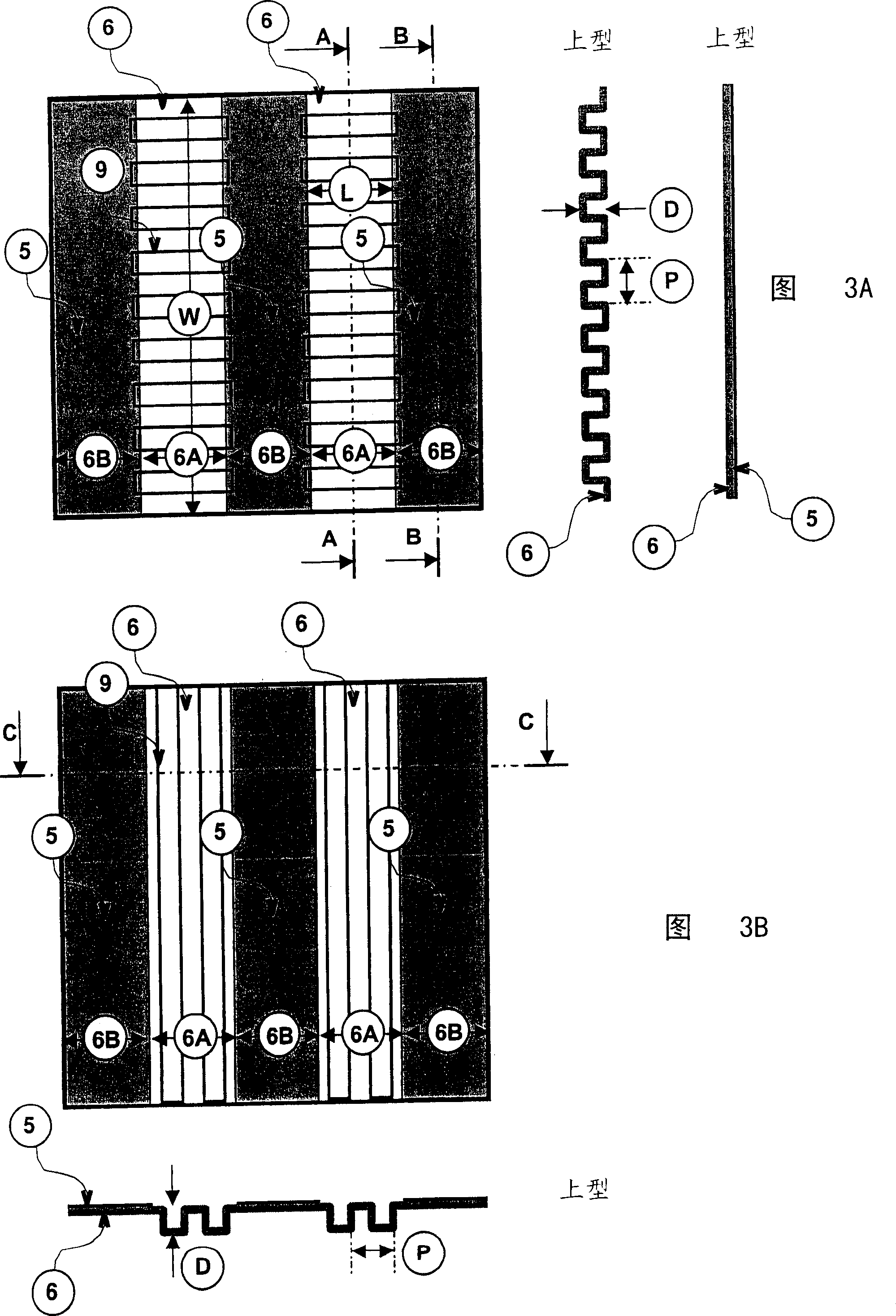
[0108] Fig. 3a thus shows the central part of the bolometer according to the invention, in particular the part sensitive to the infrared radiation to be detected by the detector.

[0109] In this central part, the parts (6A) of heat radiating material, that is to say the parts without electrodes (5), have wrinkles (9) over their entire surface, which are perpendicular to the The plane, can be seen through section A-A with respect to Fig. 3a.

[0110] These wrinkles are defined by pitch P and amplitude D. If F is defined as the ratio of the unfolded length of the corrugation (9) divided by the pitch P, except that the thermal resolution NEdT improves F 1 / 2 The use of this corrugation (9) parallel to the direction of current flow described in the embodiment will reduce the resistance R by a ratio of F, where the thickness and resistivity of the heat radiating material are unchanged.

[0111] In the embodiment shown in Figure 3b, the corrugations (9) are perpendicular to the di...


PUM


Abstract

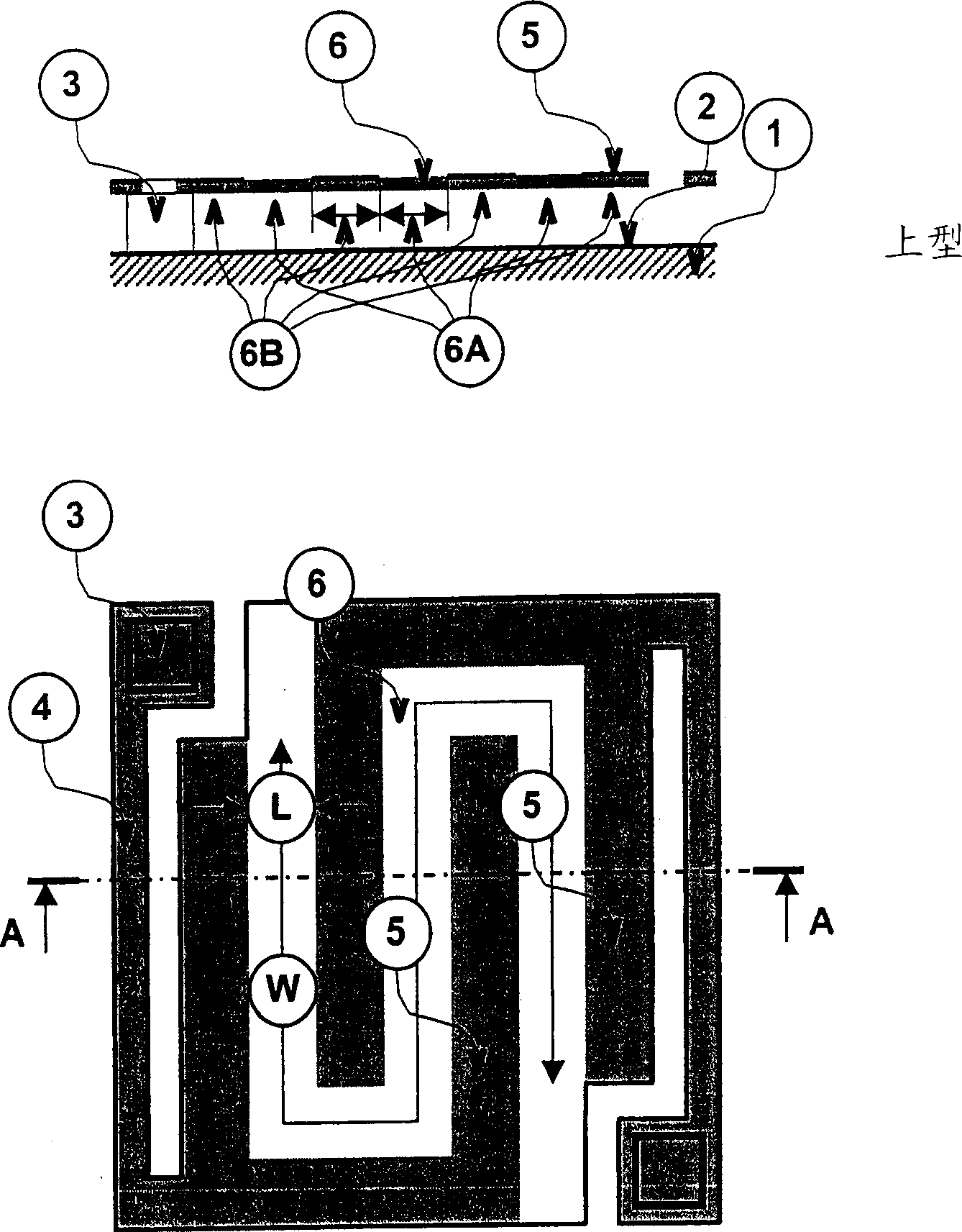
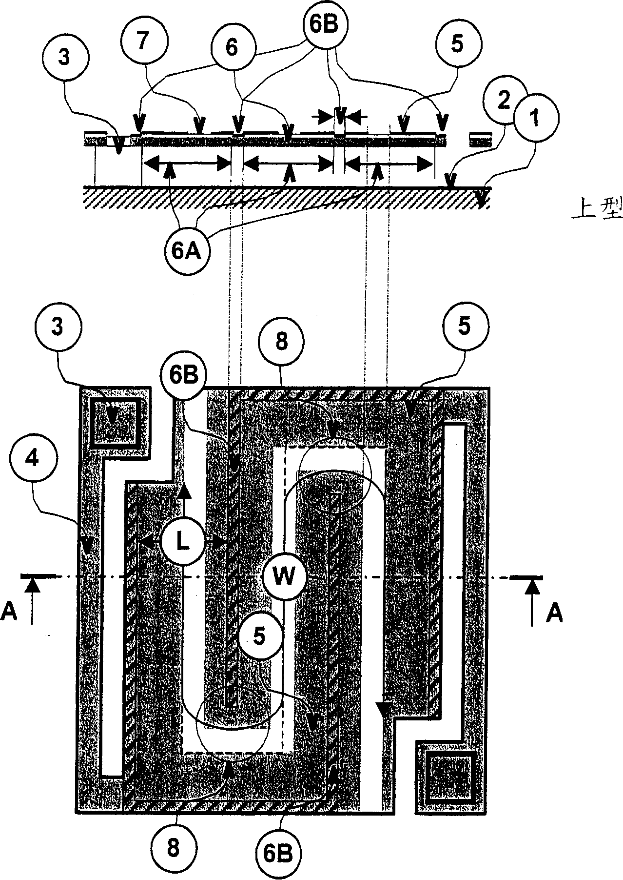
The present invention provides a bolometric detector including a sensitive part having one or more layers of a sensitive material, the resistivity of which varies with temperature, electrodes isolated from one another, also acting as infrared radiation absorbers, the electrodes being in contact with the sensitive material over at least part of their surface, at least one support region for supporting the sensitive part, acting so as to position the sensitive part, and acting as an electrical conductor, in relation to a read circuit associated with the bolometric detector, and at least one thermal insulation structure electrically and mechanically connecting each support region to the sensitive part. The regions of sensitive material not in contact with the electrodes have at least one corrugation oriented along the direction perpendicular to the plane containing the sensitive part of the bolometric detector.

Description

technical field [0001] The invention relates to a radiation heat detector and an infrared detection device using the detector. The invention also relates to the production process of the detector. [0002] The field of application of the invention is in particular in infrared imaging. Background technique [0003] Well known in the field of infrared detectors are devices arranged in arrays and capable of operating at room temperature, that is, devices that do not require refrigeration, unlike devices that inherently require very low temperatures, Usually a detection device called a quantum monitor that operates at the temperature of liquid nitrogen. [0004] Such uncooled detectors are typically varied using the physical parameters of the appropriate material (as a function of temperature in the 300K region). When using a bolometer, this physical quantity is resistivity. [0005] Such uncooled detectors typically include: [0006] Devices for absorbing infrared radiatio...

Claims


Application Information

Patent Timeline
Patent Type & Authority Applications(China)
IPC IPC(8): G01J5/20H01L27/146
CPCG01J5/20H01L27/14692H01L27/14669H01L27/14683
Inventor M·维兰
Owner ULIS SAS
Learn More