
Digital TV receiver and self-checking method

A digital TV receiving and receiving device technology, which is applied in the direction of TV, color TV, color TV parts, etc., can solve the problems of component locking error, increase channel equalizer 102g operation, increase, etc., to prevent divergence and improve Lock speed and seek function, resolve the effect that occurs

Inactive Publication Date: 2006-02-01
LEJIN GUANGDIAN ELECTRONIC CO LTD SHANGHAI
View PDF0 Cites 4 Cited by
  • Summary
  • Abstract
  • Description
  • Claims
  • Application Information

AI Technical Summary

Problems solved by technology

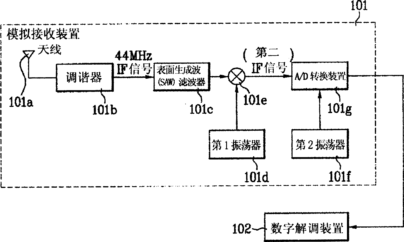
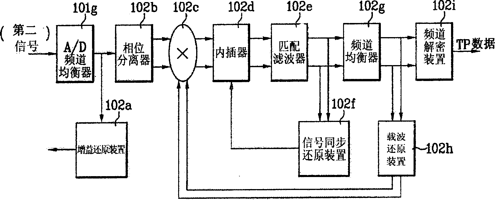
[0030] However, the existing digital television receiving apparatus as described above has the following problem: that is, since the operation is started according to the individual lock (LOCK) of each factor component, a lock error (LOCK FALSE) between components can occur, and cause system stability to be low, etc.
In the state where the received signal gain cannot be locked at an appropriate level, if the channel equalizer in the blind zone (BLIND) state operates, it will increase the possibility that the channel equalizer 102g operates in a local weak (Local Minima) state, which This characteristic is very serious for the stability of the system
[0032] In addition, because there is no training sequence (Training Sequence) in the QAM method, the signal synchronization recovery device 102f and the carrier recovery device 102h also have a high error probability
[0033] In addition, if the operation of the signal restoration device is performed according to the AGC lock signal sent from the lock detection device of the gain restoration device 102a, although these components at the rear end should continue to maintain the reset state, if the channel equalizer 102g operates, it will Increase the possibility of the channel equalizer 102g operating in a local weak (Local Minima) state, which is also very serious for the system

Method used


Image

  • Digital TV receiver and self-checking method
  • Digital TV receiver and self-checking method
  • Digital TV receiver and self-checking method

Examples


Embodiment Construction

[0066] Hereinafter, ideal examples of the PVR equipment and method designed according to the present invention will be described in detail with reference to the accompanying drawings.

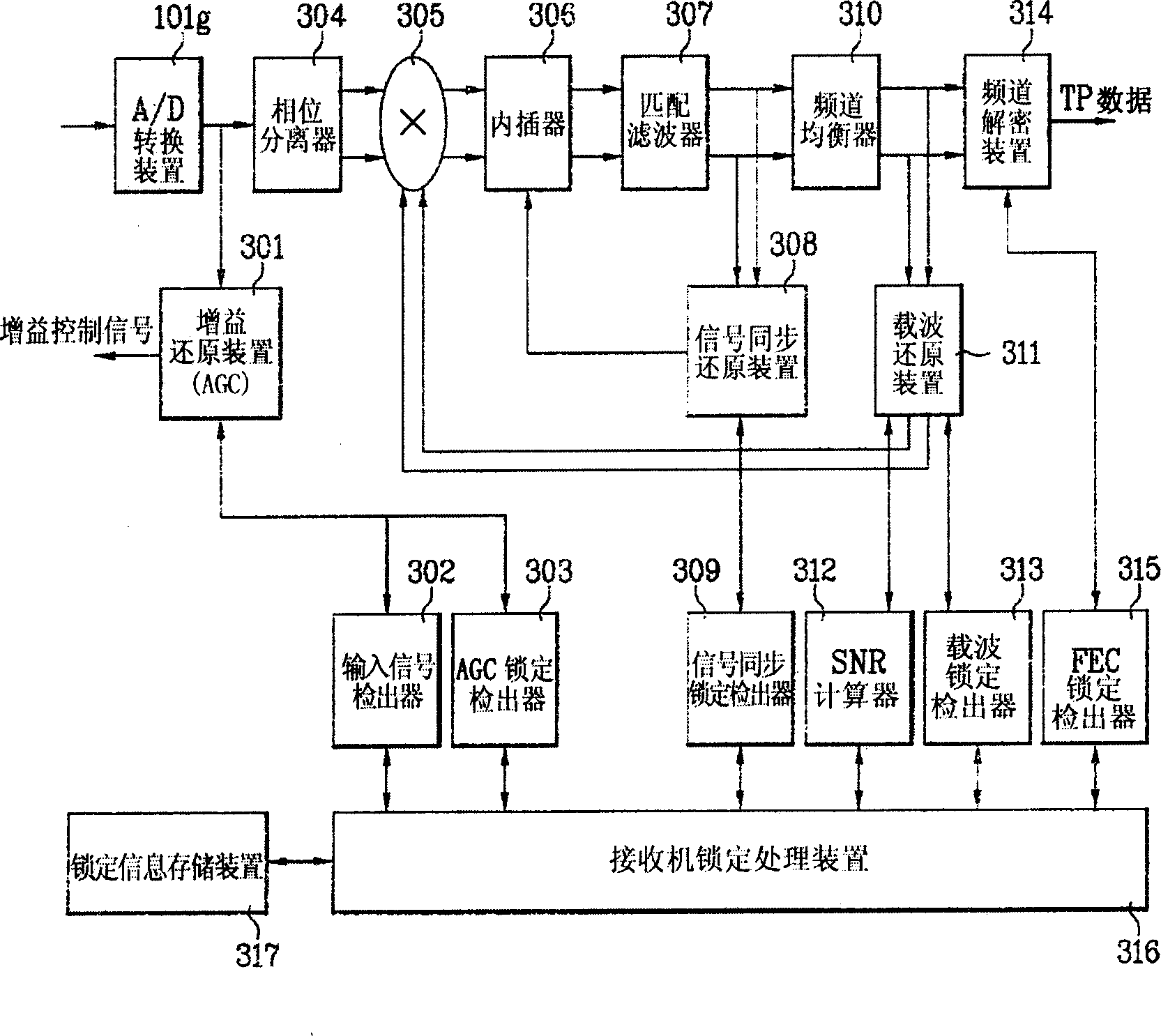
[0067] image 3 It is a constitutional diagram of a digital demodulation device according to the present invention, which consists of a gain restoration device (AGC) 301, an input signal detection device 302, an AGC lock detection device 303, a phase separator 304, a composite multiplier 305, an interpolator 306, Matched filter 307, signal synchronization restoration device (TR) 308, signal synchronization lock detection device 309, channel equalizer 310, carrier recovery device (CR) 311, SNR (Signal-to-Noise Ratio) calculation device 312, carrier lock detection Device 313, channel decryption device (FEC) 314, FEC lock detection device 315, receiving device lock processing device 316, lock information storage device 317 and other parts.

[0068] The gain restoring means 301 enhances the IF sig...


PUM


Abstract

Characters of Digital TV receiver are that the receiver in use for digital broadcasting includes multiple reduction modules composed of and including following parts: locking detection device for detecting locking signals of reduction modules; locking handle device for receiving the locking signal of the detection device, and driving the receiving devices of the reduction modules.

Description

technical field [0001] The present invention relates to digital receiving equipment, and more specifically, is about being able to solve problems such as receiving device instability / capture (Tracking) speed is low, etc. caused by false locks of various elements of digital television receiving equipment. Therefore, when a problem occurs in the receiving device, the digital television receiving device and the self-checking method thereof can be quickly checked out where the error is located. Background technique [0002] In order to conduct unified digital TV broadcasting in the future, the digital TV receiving technologies developed separately according to different transmission media (terrestrial wave, cable, satellite) are developing towards a unified system structure. [0003] Specifically, because the HDTV transmission system is utilizing the limited 6MHZ bandwidth (band-limit) to transmit data with a high bit rate (bit rate) above about 20MB / S, a modulation / demodulation...

Claims


Application Information

Patent Timeline
Patent Type & Authority Applications(China)
IPC IPC(8): H04N5/44
Inventor 李泰原
Owner LEJIN GUANGDIAN ELECTRONIC CO LTD SHANGHAI
Learn More