Last stage rotor blade of steam turbine

A technology of steam turbine and moving blade

Active Publication Date: 2006-02-08
DONGFANG TURBINE CO LTD
View PDF5 Cites 26 Cited by
  • Summary
  • Abstract
  • Description
  • Claims
  • Application Information

AI Technical Summary

Problems solved by technology

The basic structures of the above-mentioned blades are similar, and the main difference is that the structural elements (ie, characteristic parameters) of the blade structure, especially the blade body structure, are different. The specific shapes of the various compo

Method used


Image

  • Last stage rotor blade of steam turbine
  • Last stage rotor blade of steam turbine
  • Last stage rotor blade of steam turbine

Examples


Embodiment Construction

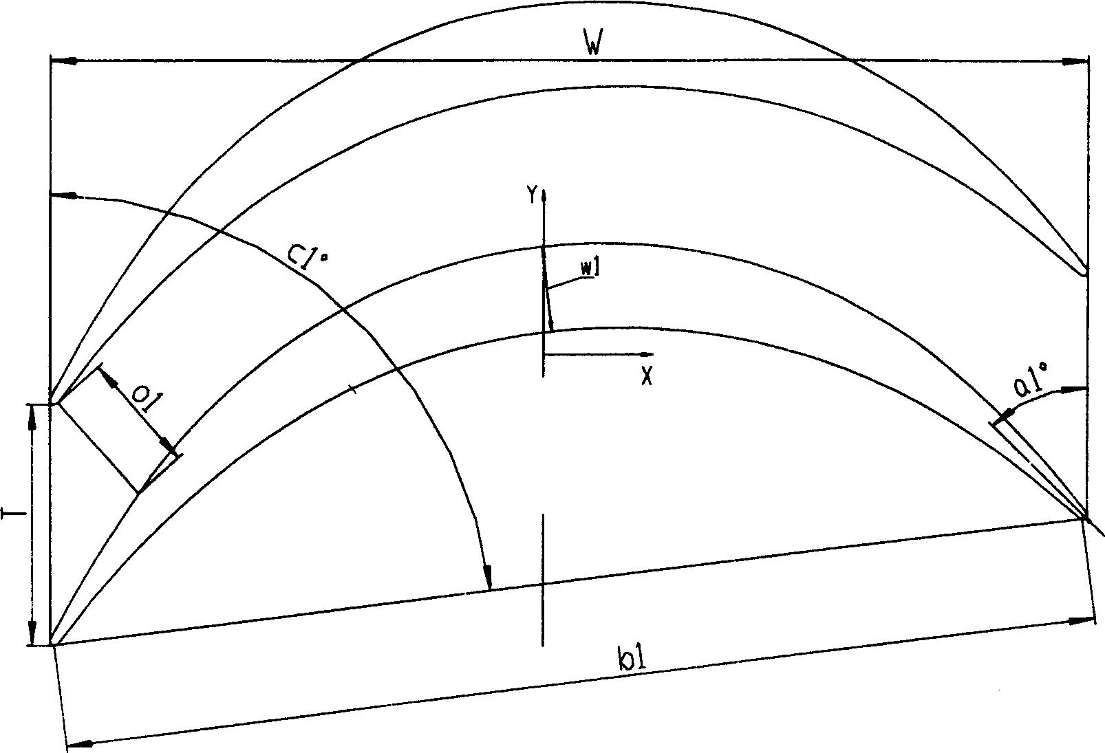
[0026] Now take the 1200mm moving blade used for 4F-1000MW class steam turbine as an example to describe the present invention in detail.

[0027] The design back pressure of the steam turbine is 5.0Kpa. Within this design back pressure range, the air passage height of the final moving blade (that is, the effective height of the blade, and the length of the blade body part) H of the final plan is 1200mm. The root diameter (that is, the diameter of the circle where the root section of the blade body is located after the blade is installed on the rotor, which is also the diameter of the rotor rim) Dr is 1905mm, and its annular area is greater than 11.6m 2 , based on the root diameter Dr and leaf height H, the flow of the low-pressure module is designed. The design principle is that the last three stages of the low-voltage are used as a building block to carry out flow-matching design. stream module. Given the low-pressure inlet pressure, enthalpy, flow rate and back pressure, o...


PUM


Abstract

The last stage movable blade of steam turbine features the relative blade height H monotonously increased from 0.0 to 1.0, blade body profile with assembling angle c1 monotonously decreased from 82.81 deg to 10.1 deg, inlet geometric angle a1 monotonously increased from 36.65 deg to 168.0 deg, outlet geometric angle a2 monotonously decreased from 31.4 deg to 10.6 deg, relative maximum thickness w1 monotonously decreased from 3.47 to 1.0, relative chord length b1 monotonously decreased from 1.84 to 1.0, relative cross section area S monotonously decreased from 7.98 to 1.0, and the ratio between blade height H to root radius of 0.5-0.7. The present invention is especially suitable for sub-critical and supercritical steam turbine with effective blade height not smaller than 1200 mm, power of 600-1200 MW and rotation speed of 3000 rpm.

Description

technical field [0001] The invention relates to steam turbine blades, in particular to a final stage moving blade of a steam turbine, which is especially suitable for subcritical and supercritical steam turbines with blade effective height ≥ 1200mm, power 600MW-1200MW, and rotating speed 3000rpm. Background technique [0002] The steam turbine is one of the three main equipments of the thermal power plant. The moving blade installed on the shaft of the steam turbine is a crucial key component in the steam turbine, especially the structural design of the final stage moving blade, because it involves a wide range of technologies, technical High content and become the core technology of steam turbines. The larger the capacity of the steam turbine and the higher the power generation density, the higher the initial parameters are required, and the larger the exhaust annular area is, the longer the final stage blade is required. The longer the final stage blade, the higher the req...

Claims


Application Information

Patent Timeline
IPC IPC(8): F01D5/14
Inventor 王为民王建录潘家成吴其林周显丁范小平曹守洪钟刚云李曦滨冯斌谢永慧孙奇赵萍李伯武黄永东袁永强
Owner DONGFANG TURBINE CO LTD
Why Eureka
Try Eureka