

Sheet type two-dimensional piezoelectric light reflection structure
A reflective structure, electro-optical technology, applied in optics, optical components, instruments, etc., can solve problems such as complex structure, achieve fast response, easy compatibility with semiconductor processing technology, and save investment.
- Summary
- Abstract
- Description
- Claims
- Application Information
AI Technical Summary
Problems solved by technology
Method used
Image

Examples
Embodiment 1
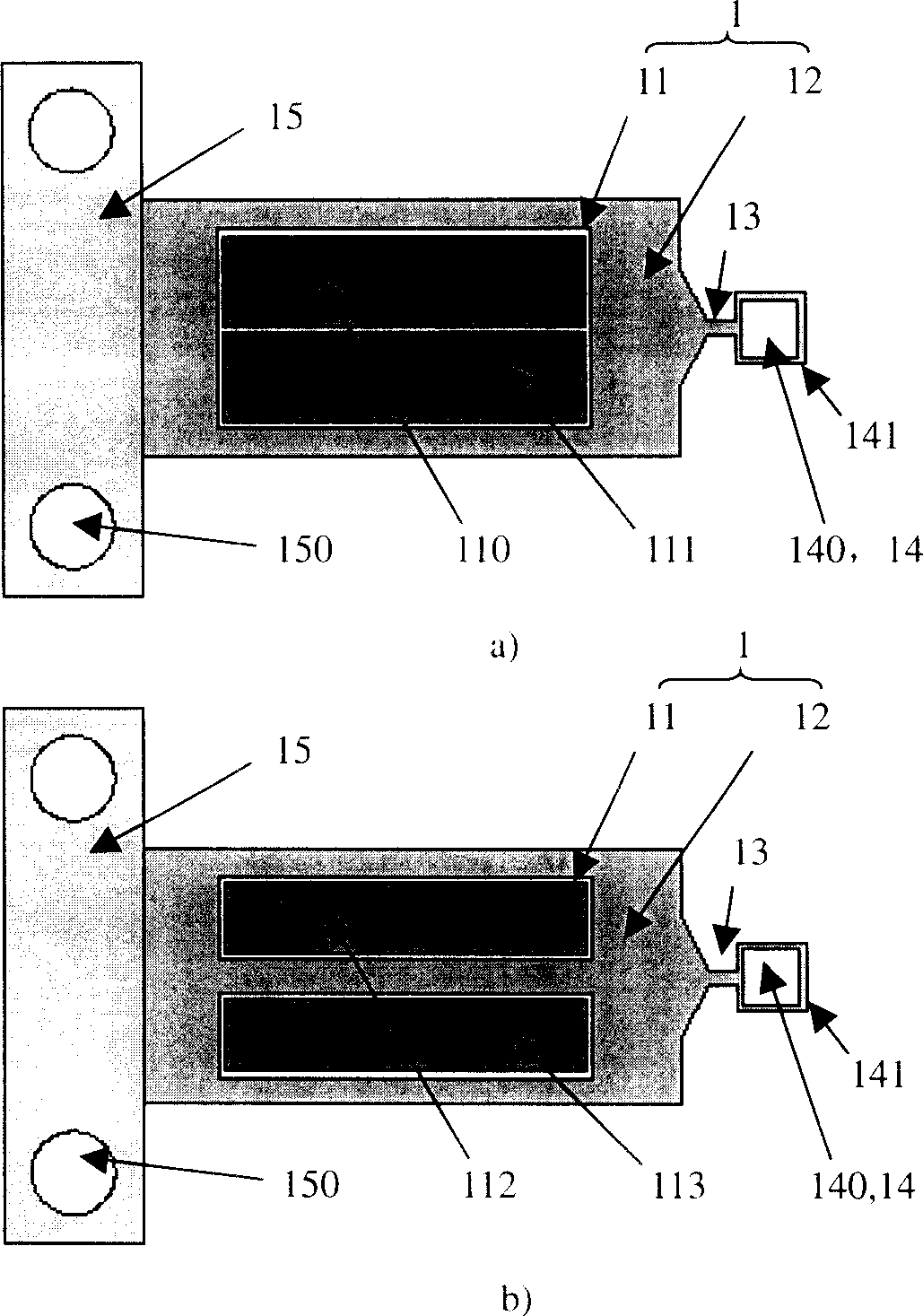
[0055] The present invention has designed the first embodiment of the sliced two-dimensional piezoelectric light reflection structure, such as Figure 1-4 shown.
[0056] The sliced two-dimensional piezoelectric optical reflection structure is composed of a composite cantilever beam 1 composed of a set of piezoelectric ceramic slices 11 and a substrate 12 , a living hinge 13 , a reflective mirror 14 , and a support frame 15 . It is characterized in that: the reflective mirror 14 is connected with the composite cantilever beam 1 through the movable hinge 13, and the composite cantilever beam 1 is fixed by the surrounding support frame 15, and 141 is a mirror frame.
[0057] The piezoelectric ceramic sheet 11 is a single-layer sheet or a multi-layer laminated sheet structure, and the polarization direction is along the thickness direction of the piezoelectric ceramic sheet 11 . The piezoelectric ceramic sheet 11 and the substrate 12 are bonded with epoxy glue, and the piezo...
Embodiment 2
[0065] The present invention has designed the second embodiment of the sliced two-dimensional piezoelectric light reflection structure, such as Figure 5 shown.
[0066] The two-dimensional piezoelectric optical reflection structure in the form of a chip is composed of a composite cantilever beam 5 composed of a group of piezoelectric ceramic sheets 51 and a substrate 52 , a living hinge 53 , a mirror 54 , 541 is a mirror frame, and a support frame 55 . It is characterized in that: the reflecting mirror 54 is connected with the composite cantilever beam 55 and the supporting frame 55 through the movable hinge 53, and the composite cantilever beam 5 is fixed by the surrounding supporting frame 55.
[0067] The piezoelectric ceramic sheet 51 is a single-layer sheet or a multi-layer laminated sheet structure, and the polarization direction is along the thickness direction of the piezoelectric ceramic sheet 51 . The piezoelectric ceramic sheet 51 and the substrate 52 are bonded...
Embodiment 3
[0075] The present invention has designed the third embodiment of the sliced two-dimensional piezoelectric light reflection structure, such as Figure 6 shown.
[0076] Chip-type two-dimensional piezoelectric light reflection structure, composed of four groups of piezoelectric ceramic sheets 610, 620, 630, 640 and substrates 611, 621, 631, 641 respectively constitute four composite cantilever beams 61, 62, 63, 64 , a living hinge 65, a mirror 66, and a supporting frame 67 are formed. It is characterized in that: four composite cantilever beams 61, 62, 63 and 64 are symmetrically distributed in a cross, reflective mirror 66 is arranged at the center point of the cross through a living hinge 65, and the four composite cantilever beams 61, 62, 63 and 64 rely on the surrounding The support frame 67 is fixed.
[0077] The piezoelectric ceramic sheets 610, 620, 630, 640 are single-layer sheets, or multi-layer laminated sheets, and the polarization direction is along the thicknes...
PUM
 Abstract
Description
Claims
Application Information