Wireless sound box

A wireless speaker and wireless connection technology, which is used in sound reinforcement systems, pulse duration/width modulation, electrical components, etc., can solve the problems of large speaker distortion and low output power, and achieve the effect of high sensitivity

Inactive Publication Date: 2006-02-15
KONKA GROUP
View PDF1 Cites 8 Cited by
  • Summary
  • Abstract
  • Description
  • Claims
  • Application Information

AI Technical Summary

Problems solved by technology

[0004] In order to overcome the disadvantages of large distortion and low output power in the speakers of existing au

Method used


Image

  • Wireless sound box
  • Wireless sound box
  • Wireless sound box

Examples


Embodiment Construction

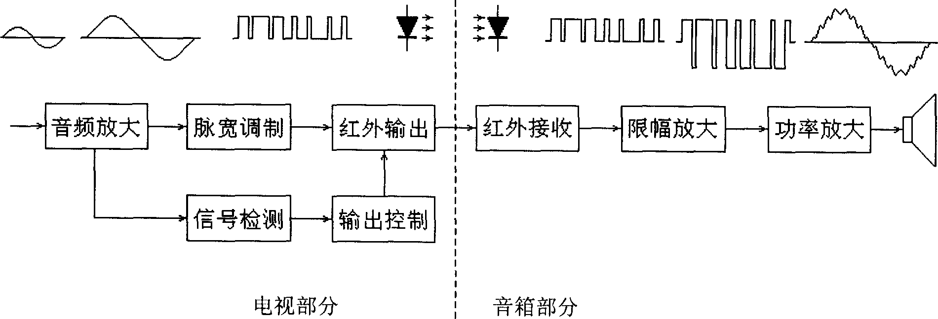
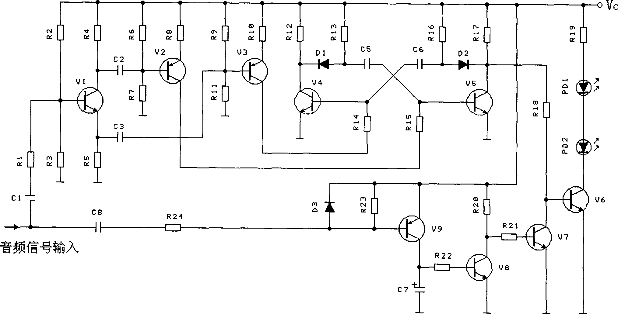
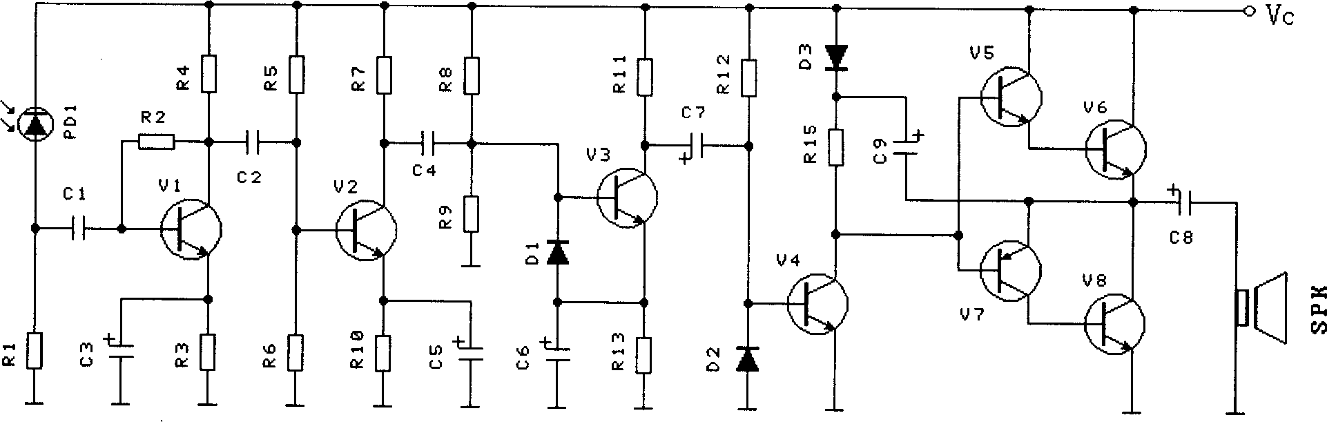
[0027] figure 1 It is a schematic block diagram of the working environment of the wireless speaker of the present invention. The wireless speaker of the present invention needs to be used in conjunction with audio-visual products such as television sets. figure 1 The two parts are shown in the middle, and the circuit part set in the TV is shown on the left, which includes audio signal modulation and infrared signal sending circuits. The diode outputs infrared light, and the brightness of the light is basically unchanged during the conduction period of the light-emitting diode, but its lighting time changes with the change of the signal. The circuit part installed in the wireless speaker is shown on the right, which includes an infrared signal receiving circuit and a limiting amplifier circuit, a power amplifier circuit and an output part (speaker). The wireless speaker communicates with the TV through wireless signals such as infrared signals.

[0028] In addition, there is...


PUM


Abstract

This invention relates to a wireless sound box wire less connected to audio visual product. Wherein, the audio signal from the audio visual product first passes the audio amplifier circuit and then the PWM circuit; the LED outputs infrared signal; arranging an infrared signal receiving circuit on the said box with back end connected with finite amplifier circuit and power amplifier circuit that drives the horn of the said box by turns. The invention has large power and less distortion and the volume is easy to regulate.

Description

technical field [0001] The invention relates to a high-power wireless sound box which forms a wireless connection with audio-visual products such as a TV set, in particular to an infrared wireless sound box. Background technique [0002] At present, the audio output power of domestic TV sets sold on the market is not large, and the output power of the speakers in the general machine is about 10 watts. With the continuous improvement of people's cultural quality, people's requirements for TV accompanying sound are also relatively improved. While continuously improving the sound quality of the TV, the sound output power must be doubled, but the speakers in the TV are generally small and the output power is limited, and when the sound power is too large, the TV will produce mechanical vibrations, causing Make other mechanical vibration sounds. In addition, the reserve power of the switching power supply in the TV is also very small, and when the sound output power is too larg...

Claims


Application Information

Patent Timeline
IPC IPC(8): H03F17/00H03F3/21H03K7/08H04R27/00
Inventor 陶显芳
Owner KONKA GROUP
Why Eureka
Try Eureka