Helical centrifugal impeller with turbofan bucket and application method of the impeller in fluid transportation

A centrifugal impeller and scoop screw technology, which is applied to turbofan scoop screw centrifugal impeller and the application field of the impeller in fluid transportation, can solve the problems of improving design without substantial breakthrough, energy loss, needing diffuser return device and the like , to achieve the effect of strong transfer and conversion ability, energy saving and wide application range

Inactive Publication Date: 2006-02-22
刘希文
View PDF1 Cites 3 Cited by
  • Summary
  • Abstract
  • Description
  • Claims
  • Application Information

AI Technical Summary

Problems solved by technology

The disadvantage is that due to the characteristics of the centrifugal impeller structure, the fluid between the two-stage centrifugal impellers, the relay transmission has a directional turn, requires a diffuser, a bend, a reflux device, and has energy loss
Compared with other background technologies, there is no substantial breakthrough and improved design, which is not enough to greatly improve the efficiency

Method used


Image

  • Helical centrifugal impeller with turbofan bucket and application method of the impeller in fluid transportation
  • Helical centrifugal impeller with turbofan bucket and application method of the impeller in fluid transportation
  • Helical centrifugal impeller with turbofan bucket and application method of the impeller in fluid transportation

Examples


Embodiment Construction

[0034] Hereinafter, the present invention will be further described through embodiments in conjunction with the accompanying drawings.

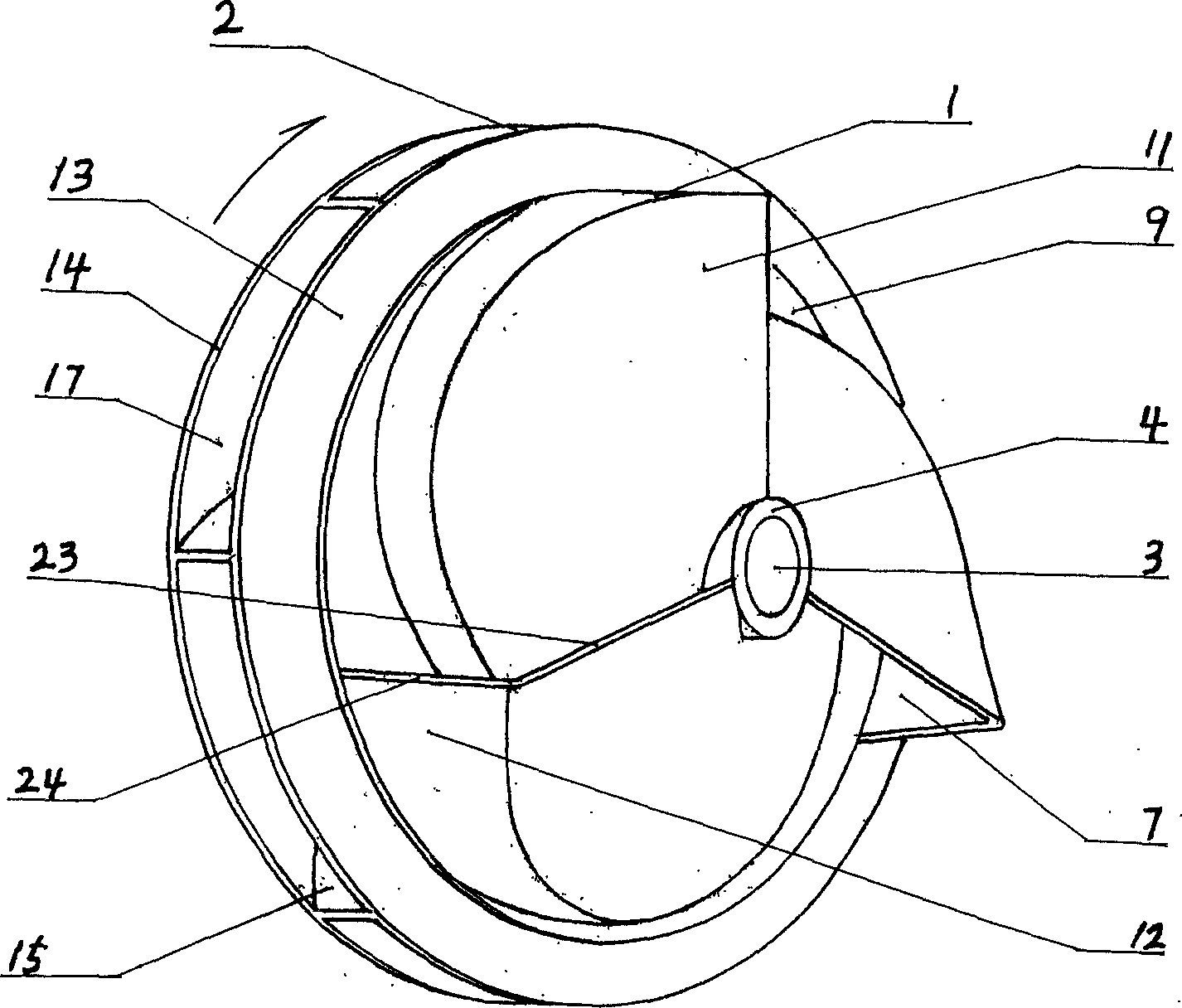
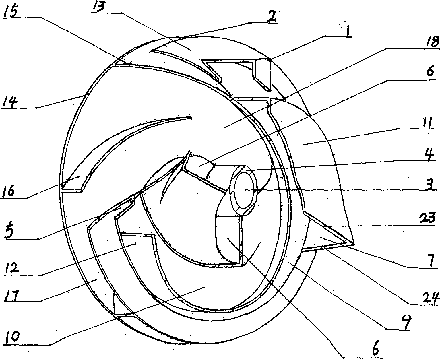
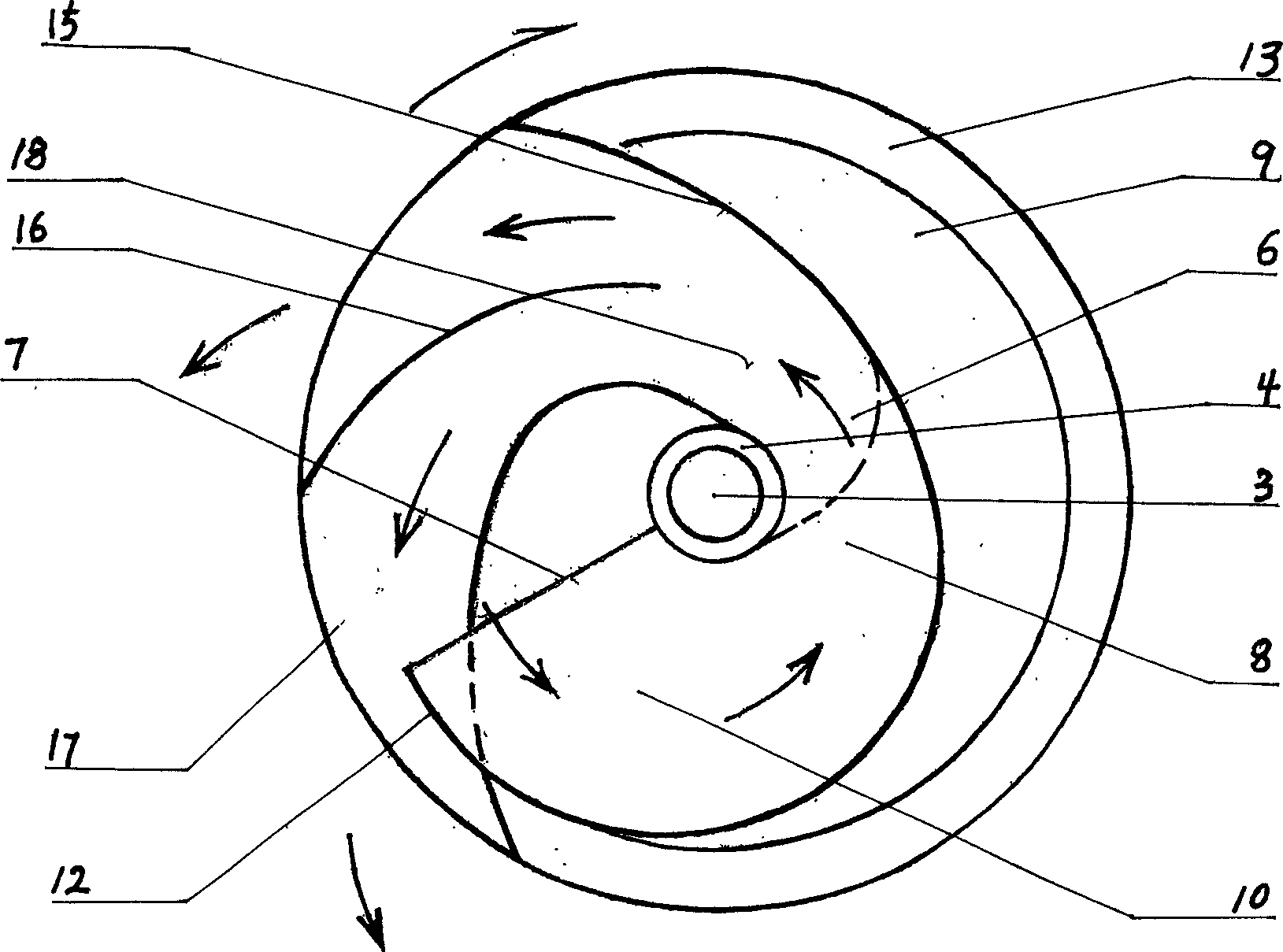
[0035] The embodiment is a turbofan bucket spiral centrifugal impeller with three main runners.

[0036] The turbofan bucket spiral centrifugal impeller consists of two stages forward and backward in the overall axial direction. The front turbofan bucket impeller is a flat cylindrical shape for the fluid cut and gathers the vortex pressure part and the back stage spiral centrifugal impeller is the fluid centrifugal thrown part. To the center of the circular surface, there is a shaft hole and a large outer diameter hub that penetrates the central axis of the front and rear impellers. Between the front stage turbofan bucket impeller and the rear stage spiral centrifugal impeller, there is an outer circle surrounding the integral impeller on the radial periphery. One-week isolation seal groove, in the radial center, there are three common main chann...


PUM


Abstract

This invention relates to a fluid conveying device, in addition to an applying method of the device in conveying, characterized in that the device comprises solid shaft front and rear two stages, and the front stage turbine fan scoop wheels are several same disks superimposed, the rear screw centrifugal impeller are several same plans; the plan whirl rectangle main channels are connected with each other to form an integrated blade wheel, making the main channels of the integrated blade wheels are rectangle turbine fan scoop wheels anticentripetal main channel whose front and rear is a twist big section surface in axial and radial. The invention has a special turbine fan scoop sprue and a radial turbine blade forming the sprue, cutting in fluid from the blade wheel excircle, making the rotating mechanical energy has stronger transforming ability to the fluid.

Description

Technical field: [0001] The present invention relates to a fluid conveying equipment and an application method of the equipment in fluid conveying, in particular to the impeller, the core working part of the blade-type fluid conveying machine, and more specifically, the turbofan bucket spiral centrifugal impeller of the present invention , Applied to vane-type fluid conveying machinery, the impeller is driven by the prime mover to rotate and work, and energy is input to the fluid to accelerate and pressurize the fluid, drive the fluid to flow, so as to achieve the function of conveying the fluid. Background technique: [0002] At present, a single fan impeller or a propeller impeller used in blade-type fluid conveying equipment and axial flow-type fluid conveying machinery operates as a fluid that is sucked in the front axially through the curved surface of the impeller blades to push and pressurize it and then output it axially backwards. The structural performance of the impell...

Claims


Application Information

Patent Timeline
Patent Type & Authority Applications(China)
IPC IPC(8): F04D29/30
Inventor 刘希文
Owner 刘希文
Why Eureka
Try Eureka