Method for operating internal combustion engine

A multi-cylinder internal combustion engine, compression stroke technology, applied in combustion engines, mechanical equipment, engine components, etc., can solve problems such as low braking pressure, and achieve the effect of improving braking power and cooling efficiency

Inactive Publication Date: 2011-06-29
AVL LIST GMBH
View PDF4 Cites 0 Cited by
  • Summary
  • Abstract
  • Description
  • Claims
  • Application Information

AI Technical Summary

Problems solved by technology

The disadvantage of this engine brake is that the achievable brake pressure is quite low

Method used


Image

  • Method for operating internal combustion engine
  • Method for operating internal combustion engine
  • Method for operating internal combustion engine

Examples


Embodiment Construction

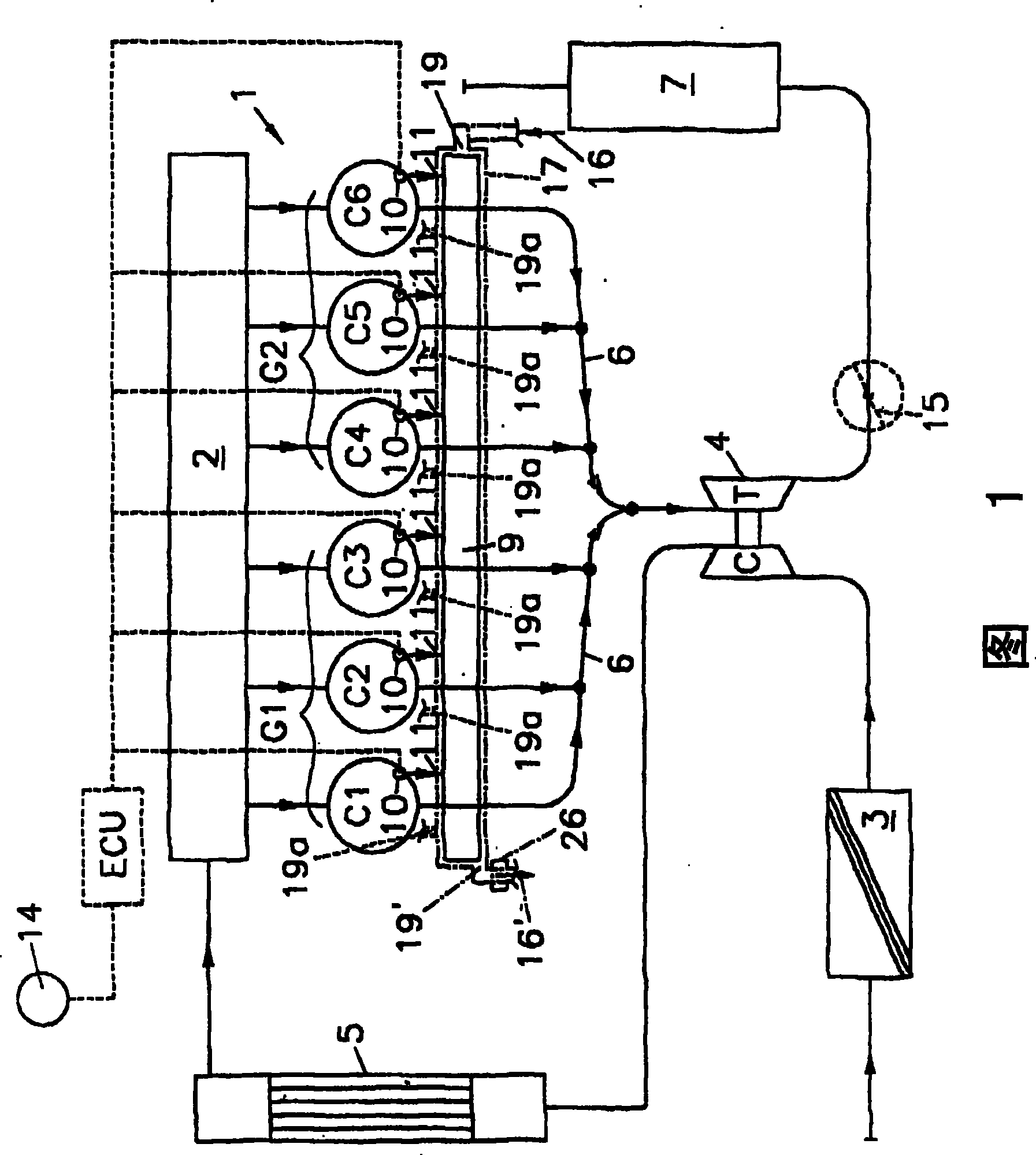
[0048] In FIG. 1, the invention is described in detail, for example with the aid of a six-cylinder turbocharged engine, wherein it should be pointed out that the function of the engine braking device according to the invention is independent of the number of cylinders and the charging system, for example, it can also be Use on unsupercharged engines.

[0049] The six cylinders C1 , C2 , C3 , C4 , C5 , C6 of the internal combustion engine 1 are connected via intake ducts (not further shown) to an intake air collector 2 , which starts from the air filter 3 via the turbocharger 4 compressor part C and supply charge air through the charge air cooler 5. The exhaust valve of the internal combustion engine 1 opens into an exhaust system 6 , wherein the exhaust gas is conveyed in a conventional manner via a turbine part T of a turbocharger 4 and discharged via a muffler 7 .

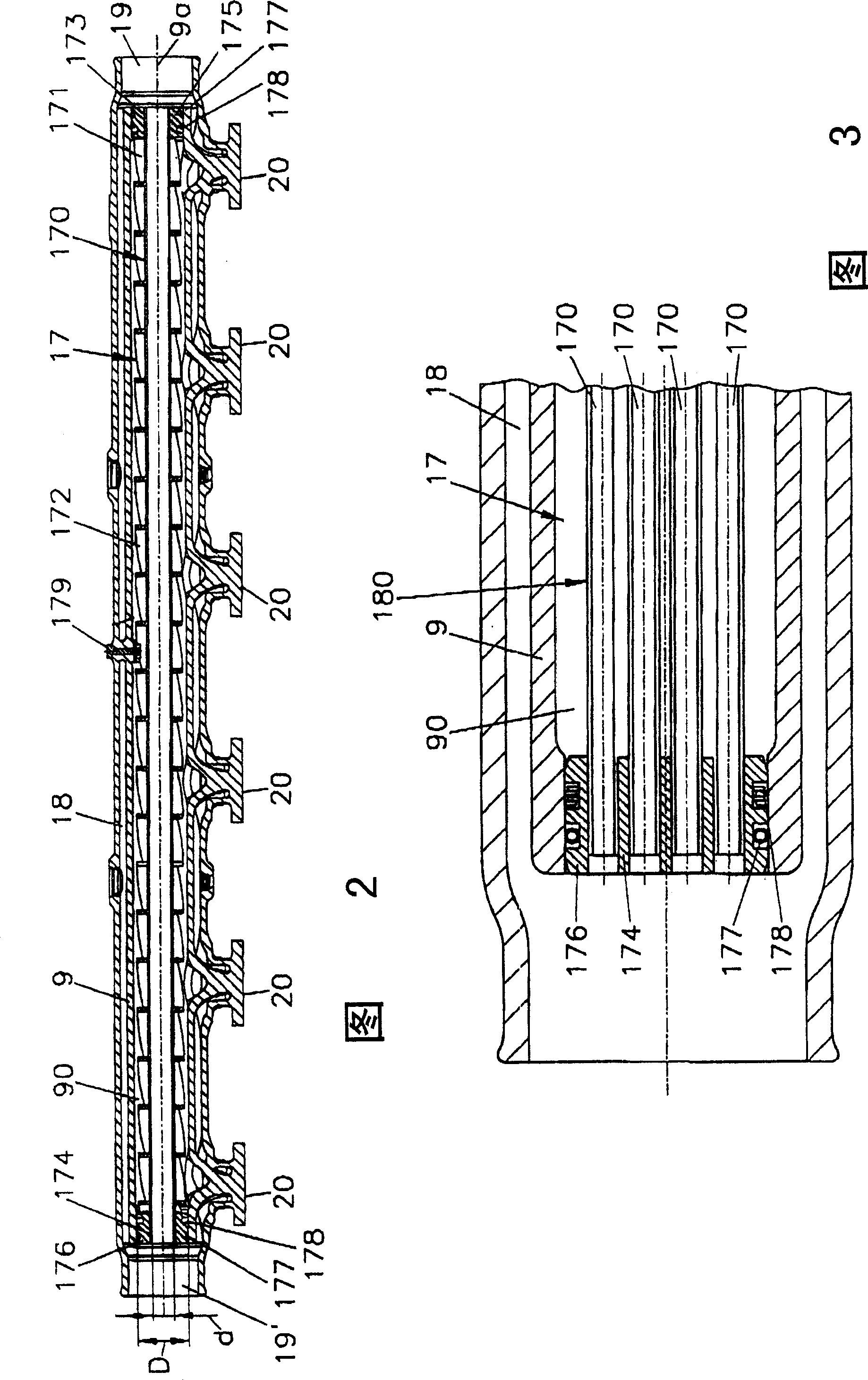
[0050] The engine brake device 8 has a tubular pressure tank 9 (brake pressure accumulator pipe), and the bra...


PUM


Abstract

The invention relates to a method for operating internal combustion engine, particularly multi-cylinder internal-combustion engine, and an engine brake mechanism. In a brake valve, each cylinder has, additionally to the input and exhaust valves, at least one brake valve which leads into a common container (brake Rail). The brake valve is at least opened once before, at the beginning and / or duringthe compression phase of the cylinder. In order to regulate the brake power in a more simple way, the brake power of the engine brake mechanism is controlled by changing the control times of the brake valve.

Description

technical field [0001] The invention relates to a method for operating an internal combustion engine, in particular a multi-cylinder internal combustion engine, and to an internal combustion engine for carrying out the method, with an engine braking device with at least one valve per cylinder, preferably connected to an intake valve and an exhaust valve. valve additional brake valve, which leads into a common pressure tank (brake pressure reservoir), wherein the brake valve is activated before, at the beginning and / or during the cylinder compression phase under engine braking Open it at least once. Background technique [0002] In particular, braking systems integrated into motor vehicles such as commercial vehicle engines are gaining in importance because these systems represent cost-effective and space-saving additional braking systems. However, increasing the specific power of modern commercial vehicle engines also requires increasing the braking power to be achieved. ...

Claims


Application Information

Patent Timeline
Patent Type & Authority Patents(China)
IPC IPC(8): F01L13/06F02D13/04F02D9/06
CPCF02D2013/0292F02D13/04F02D13/0276F02B29/0406
Inventor G·赫劳德G·奥哲博尔M·I·赛格拉卡瑞斯克H·F·西茨
Owner AVL LIST GMBH
Why Eureka
Try Eureka