Device for measuring optical fiber Raman gain coefficienct

A Raman gain coefficient, measuring fiber technology, applied in the field of optical communication devices, can solve the problems affecting gR accuracy, limited measurement range, complicated testing process, etc., and achieve the effects of no polarization dependence, wide range and good stability

Inactive Publication Date: 2006-03-22
CHINA JILIANG UNIV
View PDF0 Cites 3 Cited by
  • Summary
  • Abstract
  • Description
  • Claims
  • Application Information

AI Technical Summary

Problems solved by technology

about R The measurement of (λ) is usually measured by the small-signal gain method, that is, when a small-signal input is used, the gain is obtained by dividing the signal output of the fiber measured without a fiber laser and pumped with a fiber laser, so as to calculate the gain Measure the Raman gai...

Method used


Image

  • Device for measuring optical fiber Raman gain coefficienct
  • Device for measuring optical fiber Raman gain coefficienct
  • Device for measuring optical fiber Raman gain coefficienct

Examples


Embodiment Construction

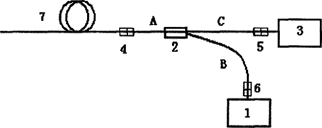
[0015] refer to figure 1 The device for measuring fiber Raman gain coefficient of the present invention comprises a fiber laser 1, a pump-signal fiber wavelength division multiplexer 2 and a fiber optic spectrometer 3, and the input terminal A of the pump-signal fiber wavelength division multiplexer 2 is connected to a useful In the first optical fiber joint 4 connected to the single-mode optical fiber 7 to be tested, the output end C of the pump-signal optical fiber wavelength division multiplexer 2 is connected to the optical fiber spectrometer 3 through the second optical fiber joint 5, and the pump-signal optical fiber wavelength division The pumping end B of the multiplexer 2 is connected to the fiber laser 1 through the third fiber connector 6 .

[0016] In the example, the measured single-mode fiber 7 connected to the first fiber optic connector 4 is a 5km DCF fiber, the pump-signal fiber wavelength division multiplexer 2 uses a 1X2 coupler, the fiber optic spectrometer...


PUM


Abstract

This invention discloses a device for measuring fiber Raman gain system including a fiber laser, a pump-signal fiber WDM and a fiber spectrometer, among which, the input of the pump-signal fiber WDM is connected with the first fiber connector for connecting with a tested single mode fiber, the output of which is connected with the spectrometer via a second fiber connector and the pump end of which is connected with the fiber laser via the third fiber connector, which does not use a signal source but applies a fiber laser as the pump source to simplify the coupling mode and increase the efficiency.

Description

technical field [0001] The invention relates to a device for measuring optical fiber Raman gain coefficient, belonging to the field of optical communication devices. Background technique [0002] In the field of optical communication S, C, L band Dense Wavelength Division Multiplexing (DWDM) optical fiber transmission system, the transmission loss can be compensated by the fiber Raman amplifier, without the need to convert the optical signal into an electrical signal in advance, directly to the optical The signal is amplified. When designing a fiber Raman amplifier, it is necessary to consider the combined effects of fiber, pump light wavelength and power, and signal light to obtain a certain gain, bandwidth and gain flatness. First, the Raman gain coefficient g of the fiber must be known R (λ), so g R (λ) measurement is very important. about R The measurement of (λ) is usually measured by the small-signal gain method, that is, when a small-signal input is used, the gain...

Claims


Application Information

Patent Timeline
IPC IPC(8): H04B10/08G01J3/28H04B10/17H01S3/30H04B10/079
Inventor 金尚忠张在宣金永兴冯春媛王剑锋刘红林李晨霞刘涛沈常宇戴碧智庄松林
Owner CHINA JILIANG UNIV
Why Eureka
Try Eureka