Laser projector

A laser projector and laser light source technology, applied in the field of laser projectors, can solve the problems of high production cost, color border, high heat, etc., and achieve the effects of fast speed, high gray level, and high light utilization rate

Inactive Publication Date: 2006-03-22
黄革雄
View PDF4 Cites 4 Cited by
  • Summary
  • Abstract
  • Description
  • Claims
  • Application Information

AI Technical Summary

Problems solved by technology

Using this method to obtain a large image, its main disadvantages or shortcomings are: 1. In terms of image quality, the brightness and contrast are insufficient, and the larger the image, the worse the brightness and contrast; Due to the influence of different refractive indices, large images are prone to color borders; the small images generated on the image source have limited precision, resulting in unclear images after enlargement; 2. In terms of use, high-brightness backlights will inevitably bring high heat and High energy consumption, poor reliability and energy-saving effect; 3. In terms of cost, to obtain the best possible image, it is necessary to use high-pixel, high-transmittance, high-heat-resistant liquid crystal panels, and high-precision lenses, so the production higher cost
[0008] 1. The scanning mechanism has poor durability;
[0009] 2. The gray level of the image is not enough, and the image definition is not good;
[0010] 3. It is impossible to take into account the needs of pure black and high brightness display in the image at the same time;
[0011] 4. There is a large mechanical noise in the scanning mechanism;
[0012] 5. The laser light source consumes a lot of energy;
[0013] 6. The durability of the laser light source is not good;
[0014] 7. The utilization efficiency of laser light source is low

Method used


Image

  • Laser projector
  • Laser projector
  • Laser projector

Examples


Embodiment Construction

[0038] figure 1 Middle: The upper figure shows that multiple red laser diodes 10 are installed on the substrate 1 and arranged in a plate shape to form a red laser light source plate 100. 100 emits multiple parallel laser beams 101, enters the converging lens group 2, and converges into a red color. The total light beam 102; the middle figure shows that a plurality of green laser diodes 20 are installed on the substrate 1 and arranged in a plate shape to form a green laser light source board 200, which emits a plurality of parallel laser beams 201, enters the converging lens group 2, and converges into a green total light beam 202; the figure below shows that multiple blue laser diodes 30 are installed on the substrate 1 and arranged in a plate shape to form a blue laser light source plate 300, which emits multiple parallel laser beams 301 and enters the converging lens Group 2, converging into a blue total light beam 302 .

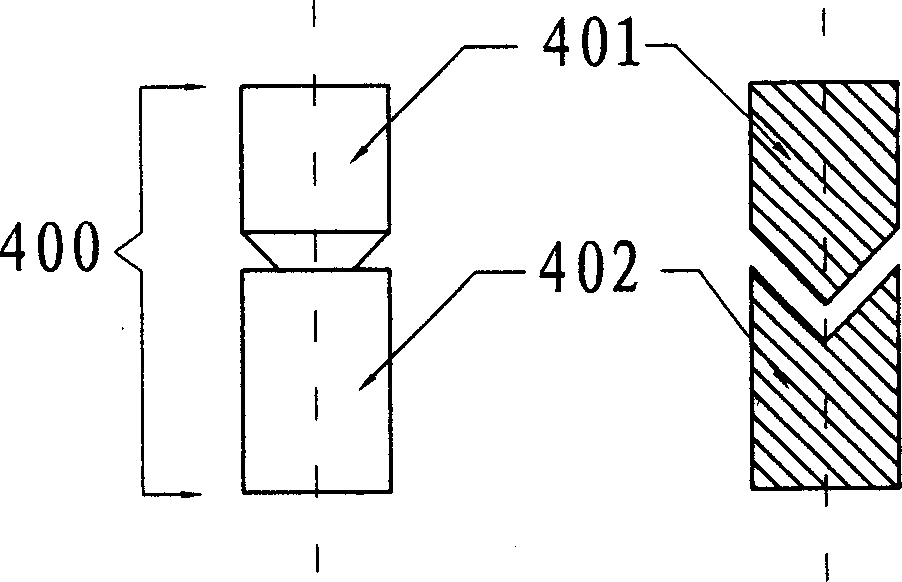
[0039] like figure 2 As shown: the convex surfac...


PUM


Abstract

This invention discloses a laser projector, which contains modulating the lighting number LED in three multistage adjustable laser light source boards of R,G,B ternary color, collecting and overlapping laser beam by collecting lens and triple prism to obtain higher image gray, two magnet suspension mechanism realizing friction free line and field scanning operation. Said invention has high resolution, low cost and energy saving.

Description

Technical field: [0001] The invention relates to an image projection device, more specifically, a laser projector. Background technique: [0002] The purpose of manufacturing a projector is to obtain a large image. The existing projectors can be divided into front projection and rear projection according to the projection direction. According to the type of image source, there are three-gun CRT tube projectors commonly used in the past, and liquid crystal projectors that are now popular. Of course, there can be many types of subdivision according to various technical characteristics, and I will not list them one by one here, because in order to obtain large images, the methods used by existing projectors are: generate images from image sources The small image of the lens is magnified and projected out to obtain a large image. Using this method to obtain a large image, its main disadvantages or shortcomings are: 1. In terms of image quality, the brightness and contrast are ...

Claims


Application Information

Patent Timeline
IPC IPC(8): H04N5/74H04N9/31
Inventor 黄革雄
Owner 黄革雄
Why Eureka
Try Eureka