Method for mfg. mould core

A manufacturing method and mold core technology, applied in the field of mold core manufacturing, can solve the problems of increasing the aggressiveness and wear of the mother sheet 14, poor adhesion of the hard film 112, and wear resistance of the mold core 11, so as to avoid temperature Uneven distribution, shortening process time, fast process effect

Inactive Publication Date: 2006-03-29
COSMOVAC IND CO LTD
View PDF0 Cites 15 Cited by
  • Summary
  • Abstract
  • Description
  • Claims
  • Application Information

AI Technical Summary

Problems solved by technology

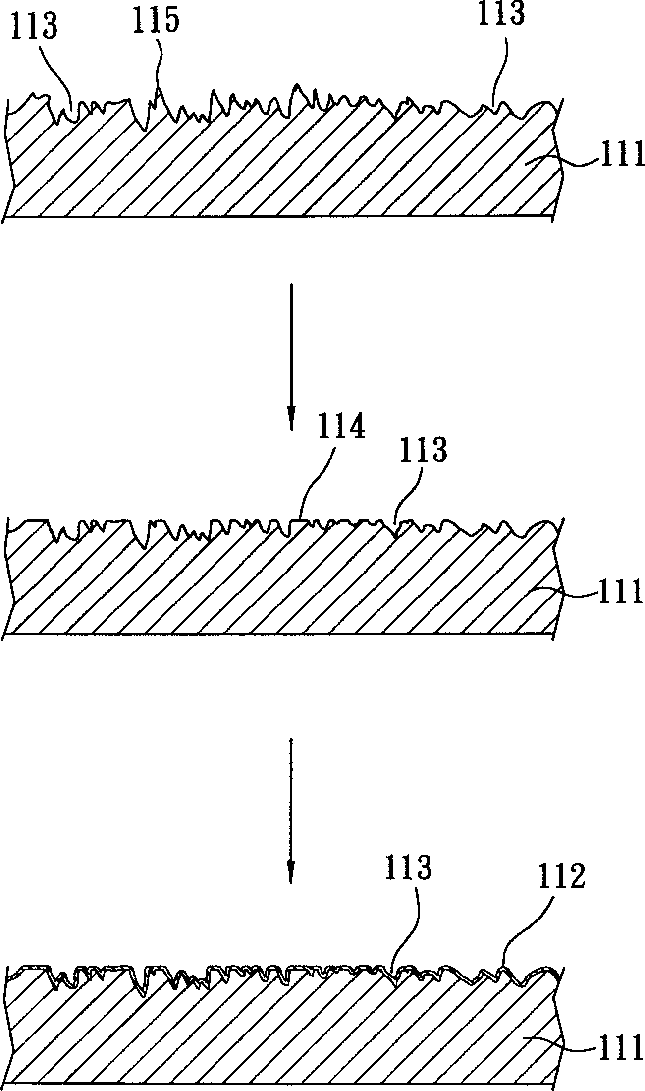
However, the inventors found that not all steel balls or ceramic balls can maintain a spherical shape during bead beating, and some broken ceramic fragments may even produce pits 113 with poor arc or sharp depressions when hitting the top surface of the template 111 , and change the local metal crystallization on the top surface of the template 111, and at the same time be embedded by the broken impact material, and because the hardness of the steel material is not high, when the steel ball or ceramic ball hits, such as Figure 5 As shown, the upper edge of the pit 113 protrudes upwards due to the pushing effect of the material during the impact to produce a hillock 116. The above conditions make it difficult to keep a smooth surface on the surface of the template 111, and also atomize the top surface of the template 111. As a result, the adhesion of the hard film 112 plated in the post-process is extremely poor, so not only the mold core 11 itself is not wear-resistant, but also increases the aggressiveness and wear of the mother chip 14

Method used


Image

  • Method for mfg. mould core
  • Method for mfg. mould core
  • Method for mfg. mould core

Examples


Embodiment Construction

[0020] For the convenience of description, in the following embodiments, similar elements are denoted by the same numerals.

[0021] Such as Figure 6 As shown, the first embodiment of the present invention provides a method for manufacturing a mold core 3, which includes the following steps:

[0022] (A) Grinding and polishing the top surface of a metal template 31 to a Ra of 0.01 μm or less to produce a smooth mirror surface on the top surface.

[0023] (B) Coating a hard film 32 on the top surface of the template 31 with a thickness of about 0.5-5 microns. The hard film 32 can be made of diamond-like carbon (DLC), tungsten carbide (WC / C), chromium nitride (CrN), titanium nitride (TiN), electroless nickel, hard chromium, etc. In this embodiment, a diamond-like carbon film is used as the material of the hard film 32 .

[0024] (C) The top surface of the template 31 coated with the hard film 32 is matched with a spherical impactor 42 with a diameter of 10-300 microns at a r...


PUM

PropertyMeasurementUnit
diameteraaaaaaaaaa
diameteraaaaaaaaaa
diameteraaaaaaaaaa

Abstract

A method for preparing the template includes such steps as polishing the top surface of a plate, plating a hard film, and using circular ball to impact on the top surface to form multiple arc pits. A mother film with information pit pattern on its surface can be stuck on said template to decrease the contact area between them and the abrasion. It can also be directly used to form a light conducting plate with high brightness.

Description

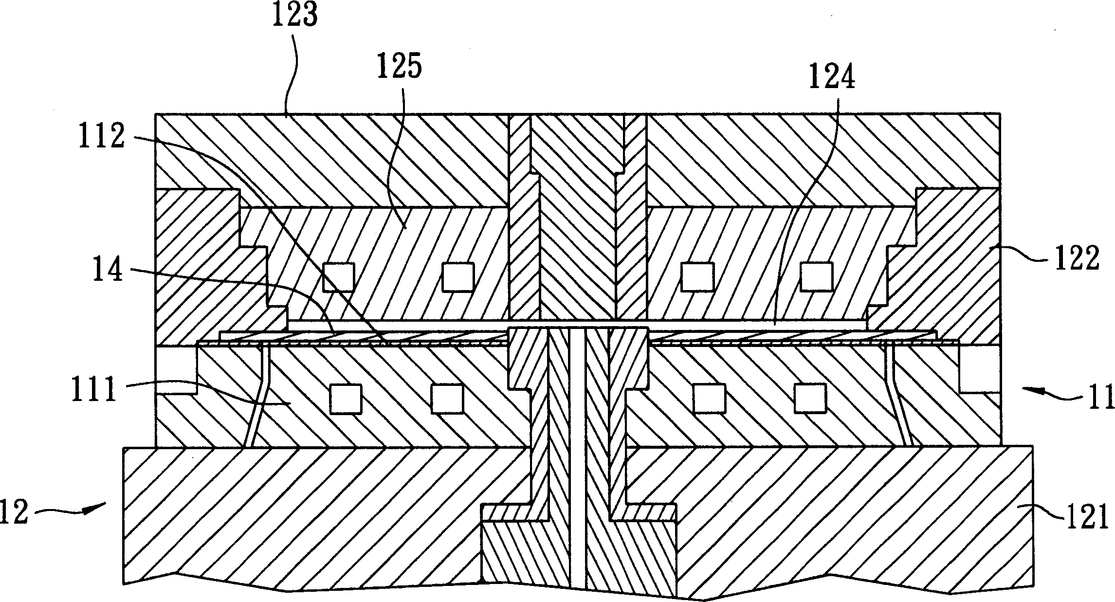
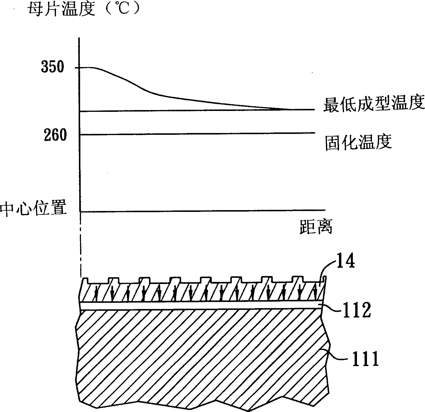
technical field [0001] The invention relates to a manufacturing method of a mold core, in particular to a manufacturing method of a mold core installed in an injection molding mold. Background technique [0002] In the general industry, injection molding machines are used to form various thermoplastic products, among which there are sheet-type products used in optoelectronic products, such as optical discs, LCD light guide plates, etc., and the mold cores used to form these products are generally called It is a "mirror mold core". The following is an example of the mold core used for forming optical discs, such as figure 1 and figure 2 As shown, the general film core 11 is installed in an injection molding mold 12, and the mold 12 has a movable mold 123 and a fixed mold 121 corresponding up and down, and an upper mold core plate 125 fixed on the bottom surface of the movable mold 123, And a frame 122 arranged on the periphery. The mold core 11 is installed on the top sur...

Claims


Application Information

Patent Timeline
Patent Type & Authority Applications(China)
IPC IPC(8): B23P13/00B23P9/04B29C33/38B29C45/26
Inventor 王冠宇潘绲玉
Owner COSMOVAC IND CO LTD
Why Eureka
Try Eureka