Electron ballast passive power factor correcting circuit

A technology of passive power factor and electronic ballast, which is applied in the direction of electric light source, AC power input conversion to DC power output, output power conversion device, etc., which can solve the problems that integrated fluorescent lamp components cannot be used and the cost is high. Achieve the effect of simple structure and improved life

Active Publication Date: 2006-03-29
DONGYANG TOSPO LIGHTING
View PDF0 Cites 5 Cited by
  • Summary
  • Abstract
  • Description
  • Claims
  • Application Information

AI Technical Summary

Problems solved by technology

[0002] The electrical pollution problem of electrical appliances in the world is becoming more and more prominent. With the increasing application of electronic ballasts, the requirements for them are getting higher and higher. In response to the national requirements for green lighting, the purification of electronic and electrical equipment and power grids Pollution rate, promote the healthy development and popularization and application of energy-saving lighting electronic and electrical products, in order to achieve the purpose of saving energy and protecting the environment. The new national standard (3C standard) has very high requirements for the power factor and harmonics of electronic ballasts. For this reason, some foreign companies have developed some special PFC correction chips, such as ST's 6561, 6560, IRF's 2151, etc., which can meet the new national standard requirements in terms of power factor (PF) and harmonics, but require more Too many peripheral components make the cost price very high, and it is impossible to apply in the integrated fluorescent lamp due to too many components, which affects further promotion

Method used


Image

  • Electron ballast passive power factor correcting circuit
  • Electron ballast passive power factor correcting circuit
  • Electron ballast passive power factor correcting circuit

Examples


Embodiment Construction

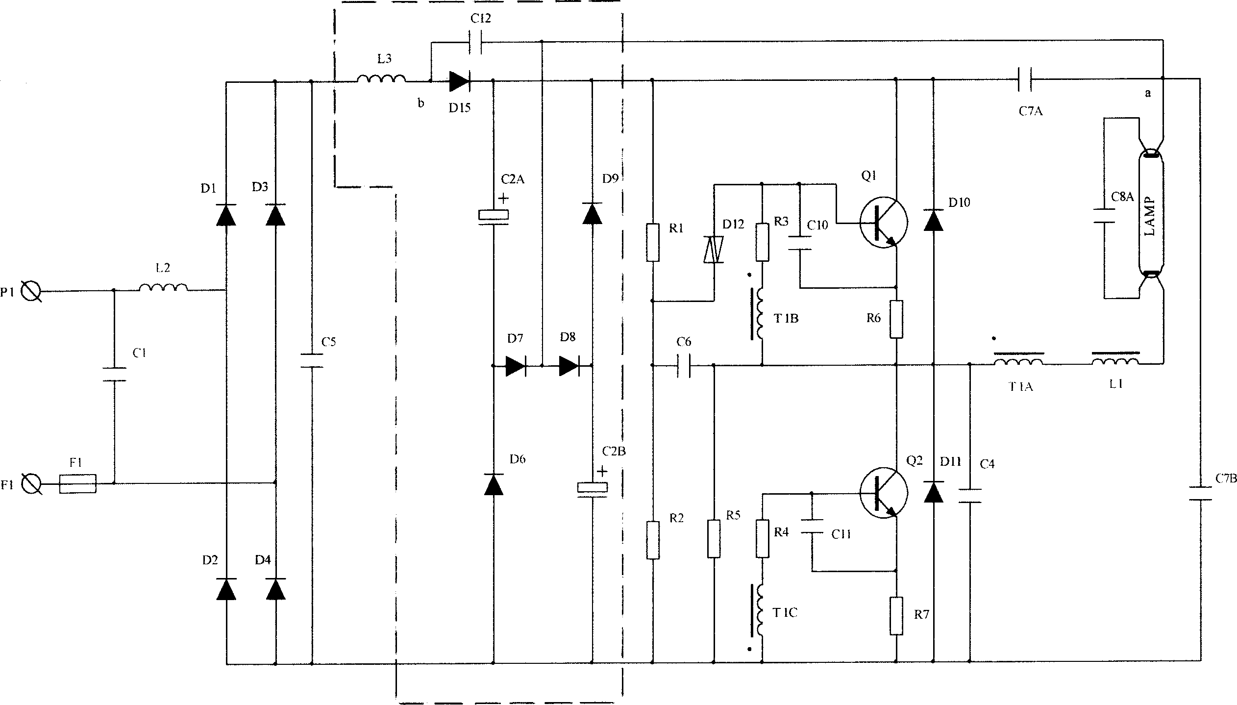
[0017] refer to figure 1 , the electronic ballast circuit includes a power input circuit, a passive power factor correction circuit and a DC / AC conversion circuit, wherein the power input circuit includes a filter circuit composed of capacitor C1 and inductor L2 and a filter circuit composed of D1, D2, D3, D4 Full-wave rectification circuit and capacitor C5. The DC / AC conversion circuit includes a resistor R1, a resistor R2, a resistor R3, a resistor R4, a resistor R5, a resistor R6, a resistor R7, a capacitor C4, a capacitor C6, a capacitor C10, a capacitor C11, a DC blocking capacitor C7A, and a DC blocking capacitor C7B, capacitor C8A, diode D10, diode D11, bidirectional trigger diode D12, oscillating coil T1A, oscillating coil T1B, oscillating coil T1C, inductor L1, transistor Q1 and transistor Q2.

[0018] The passive power factor correction circuit includes a BOOST circuit and a flow-by-stream circuit. The BOOST circuit includes an inductor L3, a capacitor C12 and a di...


PUM


Abstract

There is disclosed a passive power-factor correcting circuit for the electronic ballast, which includes BOOST circuit consisting of an inductor, a capacitor and a diode, and a current-follower circuit consisting of two electrolytic capacitors and four diodes. The BOOST circuit is series connected between the mains output circuit of the electronic ballast and the lead-in end of the filament. The current-follower circuit is parallel connected at the front end of DC / AC translation circuit of the electronic ballast.

Description

technical field [0001] The invention relates to an input power factor correction circuit of an electronic ballast, in particular to a circuit for achieving high PF correction by using a small number of passive components. Background technique [0002] The electrical pollution problem of electrical appliances in the world is becoming more and more prominent. With the increasing application of electronic ballasts, the requirements for them are getting higher and higher. In response to the national requirements for green lighting, the purification of electronic and electrical equipment and power grids Pollution rate, promote the healthy development and popularization and application of energy-saving lighting electronic and electrical products, in order to achieve the purpose of saving energy and protecting the environment. The new national standard (3C standard) has very high requirements for the power factor and harmonics of electronic ballasts. For this reason, some foreign c...

Claims


Application Information

Patent Timeline
IPC IPC(8): H05B41/14H02M7/538H02M1/12H02M1/14
Inventor 陈欣平马锦洪
Owner DONGYANG TOSPO LIGHTING
Why Eureka
Try Eureka