Slm direct writer

A spatial light modulator, sub-exposure technology, applied in optics, instruments, optomechanical equipment, etc., can solve the problems of complex and high chip complexity

Active Publication Date: 2006-03-29
MICRONIC LASER SYST AB
View PDF3 Cites 3 Cited by
  • Summary
  • Abstract
  • Description
  • Claims
  • Application Information

AI Technical Summary

Problems solved by technology

However, the complexity of modern chips is extremely...

Method used


Image

  • Slm direct writer
  • Slm direct writer
  • Slm direct writer

Examples


Embodiment Construction

[0021] The following detailed description is made with reference to the accompanying drawings. The preferred embodiments are described in order to illustrate the invention, not to limit its scope as defined by the claims. Those skilled in the art will recognize numerous equivalent variations to the description below.

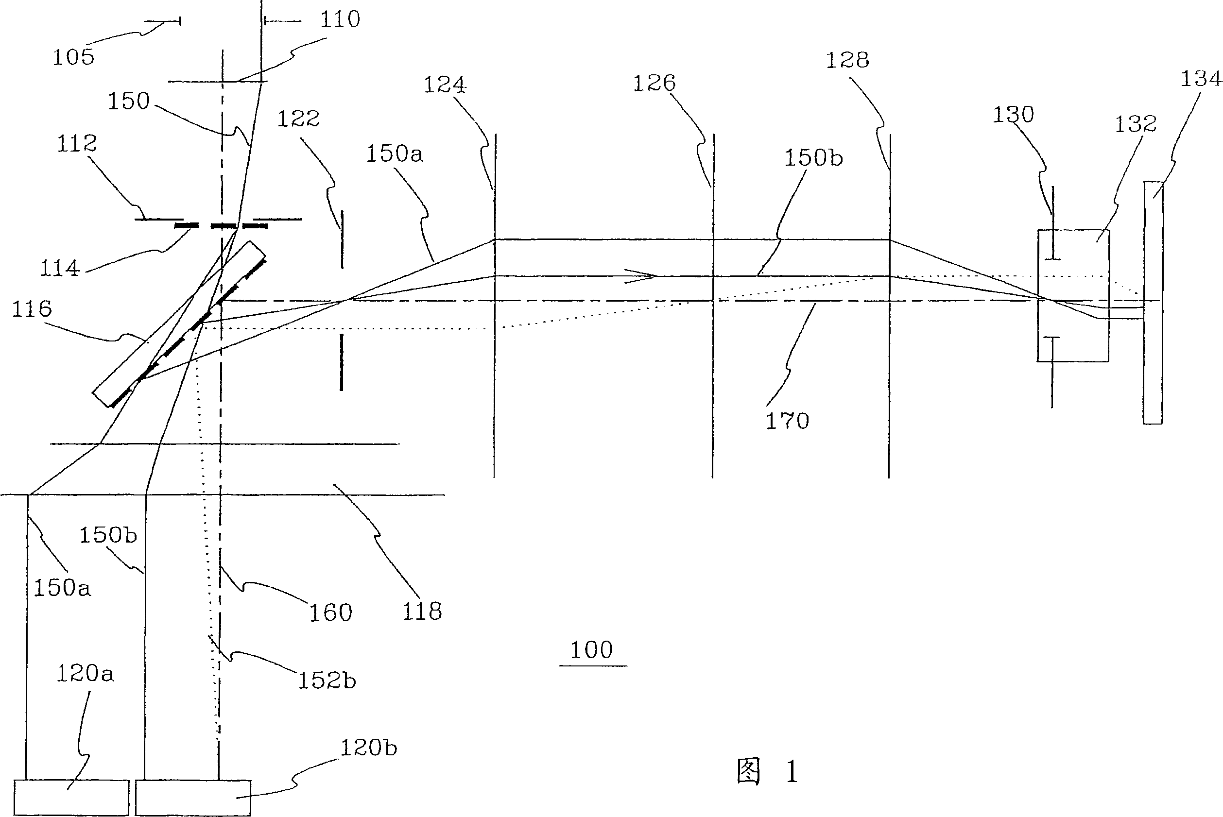
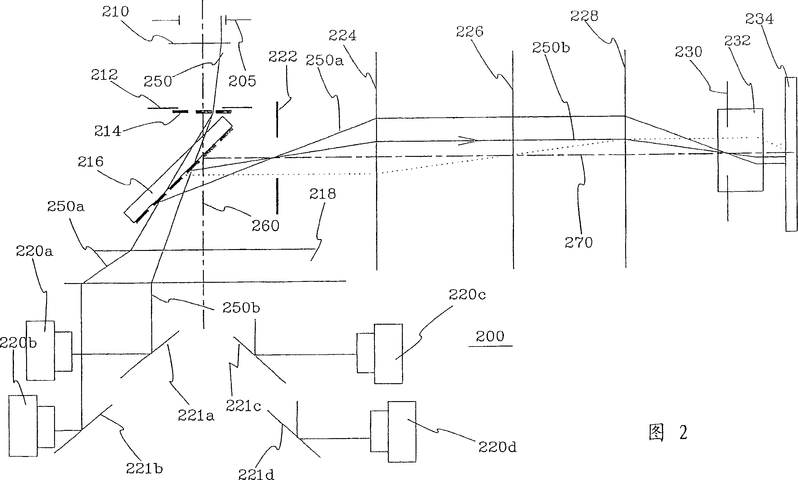
[0022] Furthermore, the preferred embodiments are described with reference to an analog spatial light modulator. It will be obvious to those skilled in the art that there may be situations where other spatial light modulators than analog spatial light modulators are equally applicable; for example digital spatial light modulators like the Digital Micromirror Device (DMD) manufactured by Texas Instruments. Modulator. Additionally, SLMs can be composed of reflective or transmissive pixels. Furthermore, preferred embodiments are described with reference to excimer laser sources. Obviously for those skilled in the art, the present invention method can use the pu...


PUM


Abstract

The present invention relates to an apparatus (100) for patterning a workpiece arranged at an image plane and sensitive to electromagnetic radiation, comprising a source emitting electromagnetic radiation onto an object plane and at least two spatial light modulators each comprising numerous of object pixels, adapted to receive said electromagnetic radiation at said object plane and to relay said electromagnetic radiation toward said workpiece, wherein said electromagnetic radiation is split into at least two beams, which beams will impinge on different spatial light modulators, by a beam splitting device arranged at an optical plane between said spatial light modulators and an illuminator pupil or a conjugate optical plane. The invention also relates to a method for patterning a workpiece with a plurality of spatial ight modulators.

Description

technical field [0001] The present invention relates to laser lithography technology, in particular to a method and a device for directly writing patterns using a spatial light modulator (SLM). Background technique [0002] Modern ultraviolet (UV) lithography is seeking new highly parallel writing schemes. Spatial light modulators (SLMs) with optional microelectromechanical systems (MEMS) offer this possibility. SLM chips may include DRAM-like CMOS circuits with millions of individually addressable pixels on them. The pixels are deflected due to the electrostatic force difference between the mirror unit and the address electrodes. A pattern generator utilizing a spatial light modulator is described in US 6373619 assigned to the assignee of the present invention. The patent briefly discloses a small field stepper that exposes a set of images of a spatial light modulator. The workpiece is positioned on a continuously moving stage, and a source of pulsed electromagnetic rad...

Claims


Application Information

Patent Timeline
IPC IPC(8): G03F7/20
CPCG03F7/70291G03F7/20
Inventor 托比约恩·桑德斯特罗姆
Owner MICRONIC LASER SYST AB
Why Eureka
Try Eureka