
Self-modulating inert gas gire suppression system

A technology for gas and gas regulation, applied in pipeline systems, gas treatment applications, gas/liquid distribution and storage, etc., can solve expensive and other problems, and achieve the effect of economic advantages

Inactive Publication Date: 2006-04-05
FIKE CORP
View PDF0 Cites 10 Cited by
  • Summary
  • Abstract
  • Description
  • Claims
  • Application Information

AI Technical Summary

Problems solved by technology

The required 160-wall pipe is obviously much more expensive than 40-wall pipe, and roughly 0.3 meters of 160-wall pipe is required per inert gas container

Method used


Image

  • Self-modulating inert gas gire suppression system
  • Self-modulating inert gas gire suppression system
  • Self-modulating inert gas gire suppression system

Examples


Embodiment Construction

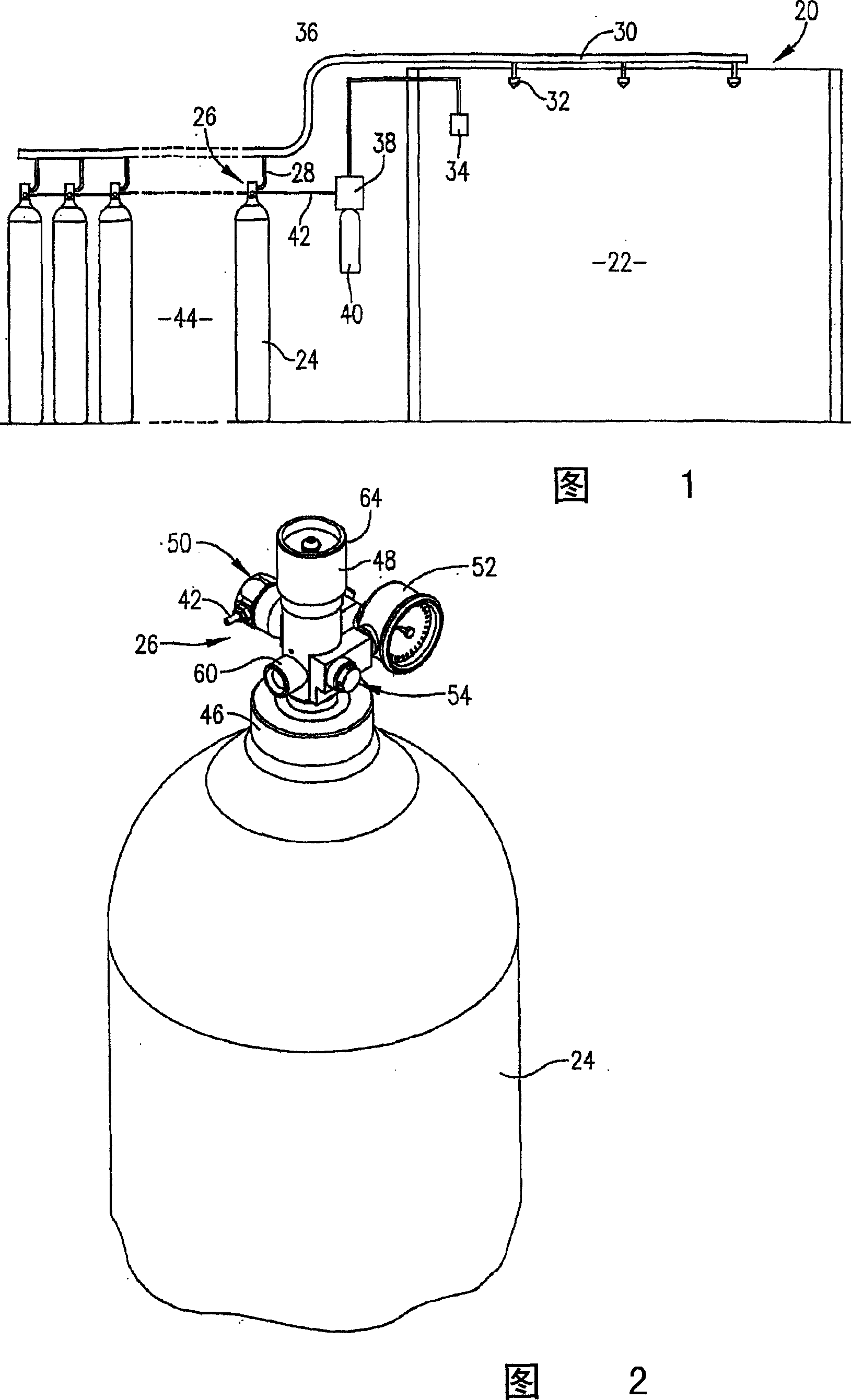
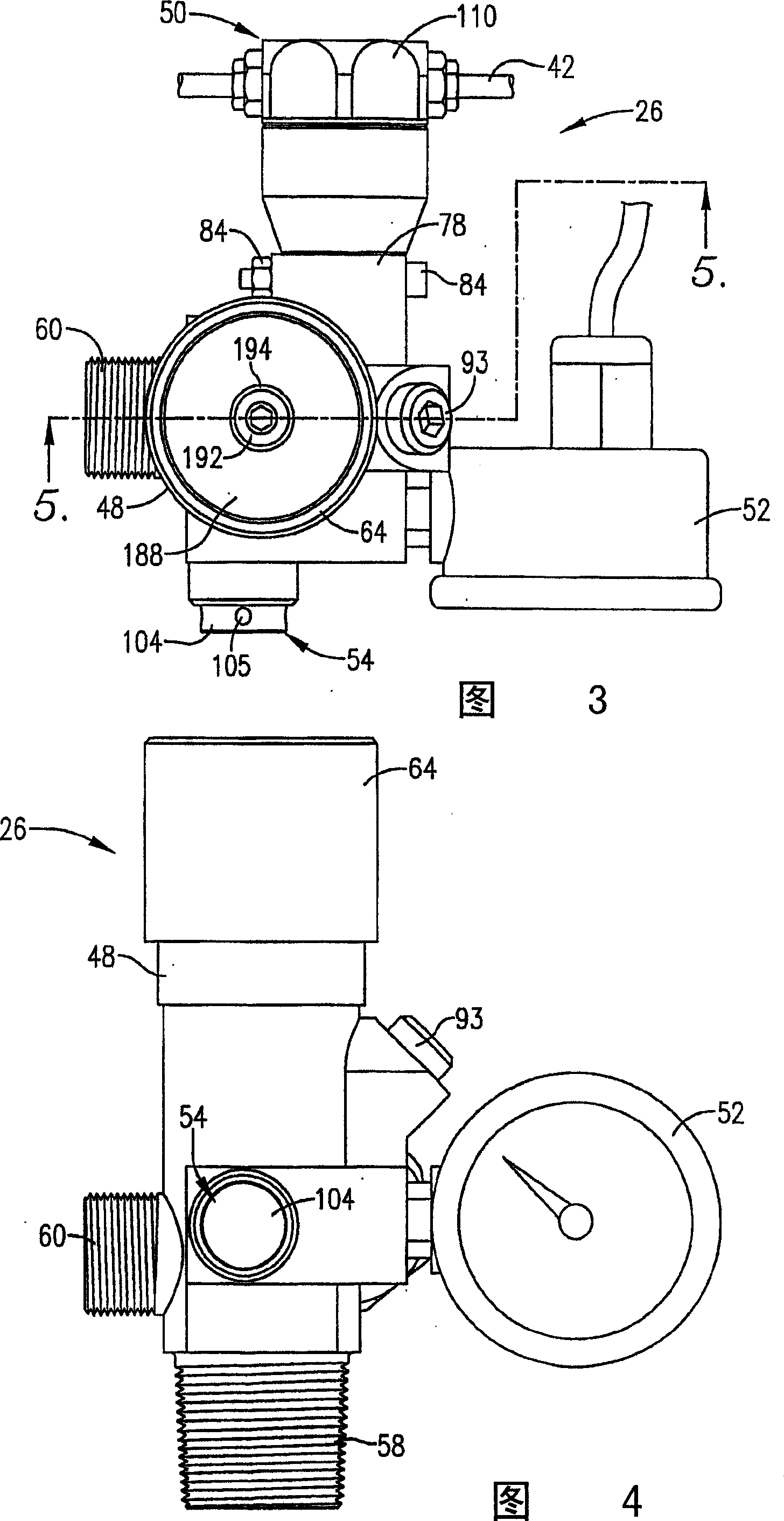
[0029]Referring now to the drawings, a hazard suppression system 20 is schematically shown in FIG. 1 . System 20 is designed to protect an enclosed room 22 where computer equipment or other valuable equipment may be housed. Generally, the system 20 includes a plurality of high pressure inert gas cylinders 24 each containing a valve unit 26 . Each valve unit 26 is connected to a manifold assembly 30 by a conduit 28 . As shown, assembly 30 extends into room 22 and incorporates a plurality of nozzles 32 for delivering inert gas into room 22 to suppress hazards. The piping that makes up the system 30 may be conventional 40 gauge pipe, as opposed to the heavy duty 160 gauge manifolds and pressure reducing orifice plates required by prior art systems of this type. The overall system 20 also includes a hazard detector 34 connected by a cable 36 to a solenoid valve 38 . Solenoid valve 38 is operably connected to a small gas cylinder 40, typically containing pressurized nitrogen or ...


PUM


Abstract

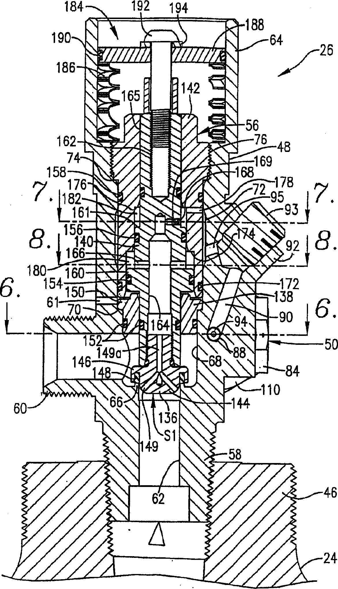
The invention relates to a valve unit (26). The valve unit (26) comprises a valve body (48) presenting an inlet (58) adapted for coupling with a source of pressurized gas (24) and an outlet (60) adapted for coupling with a gas receiver (30), and a shiftable valve member (56). The shiftable valve member (56) includes a piston seal holder (136) and an inner body section (140), and the shiftable valve member is located within said body (48) between said inlet (58) and said outlet (60) and is shiftable between a closed, gas flow-blocking position and a valve open position permitting flow of gas from said source (24) to said receiver (30). Said member (56) is normally maintained in said closed position against a valve opening force exerted there against by said source of pressurized gas (24). The valve unit (26) further comprises a spring (186) located within a spring chamber (64) operable to bias said inner body section (140) toward the valve open position, a first operating surface (S1) forming a part of said piston seal holder (136) that is exposed to said pressurized gas from said source (24), a modulation chamber (182) formed between at least a part of a second operating surface (S2) and adjacent portions of said valve body (48), a passageway (168) communicating said source (24) with said modulation chamber, pressurized gas from said source (24) exerting a valve closing force on said second operating surface (S2), and an actuator (50) operable upon actuation thereof to cause said shiftable valve member (56) to shift to the valve open position, gas from said source (24) to be delivered to said receiver, and gas from said modulation chamber to be drained therefrom.

Description

technical field [0001] The present invention relates to an inert gas hazard suppression assembly for protecting an area or room, such as a computer equipment room, from hazards, especially fire. More particularly, the present invention relates to a system, and a pressure regulating inert gas valve forming part thereof, in which a plurality of high pressure inert gas cylinders are used and each cylinder is provided with a valve unit, the valve The unit is operable to deliver a relatively low pressure inert gas at a substantially constant pressure for most of the time the gas is delivered, thereby providing effective hazard suppression without the high pressure gas typically required by prior art inert gas hazard suppression systems Processing and dispensing equipment or pressure reducing orifice. Each valve unit includes a spring assembly that biases the valve unit toward an open position allowing gas flow and a gas flow regulation circuit that maintains the gas pressure at ap...

Claims


Application Information

Patent Timeline
Patent Type & Authority Applications(China)
IPC IPC(8): B05B1/30A62C8/00A62C35/68A62C99/00F17C13/04F17D3/00F17D5/00G08B
CPCF17C2250/0636F17C2270/07F17C2201/0109F17C2250/036F16K31/406F17C13/04F16K1/305A62C99/0018F17C2201/056F17C2221/013F17C2250/043F17C2223/036F17C2270/05F17C2221/016F17C2270/0754F17C2221/014F17C2201/058F17C2205/0385F17C2205/0394F17C2223/0123F17C2205/0326A62C35/68F17C2250/032F17C2201/032B05B1/30F17D3/00F17D5/00
Inventor B·T·斯帝威尔M·J·肯特D·N·帕特尔K·L·古多尔
Owner FIKE CORP
Learn More