Plate heat exchanger

A technology of plate heat exchangers and heat exchangers, applied in the direction of indirect heat exchangers, heat exchanger types, heating methods, etc., can solve problems such as large energy consumption, and achieve the effect of easy maintenance and simple structure

Inactive Publication Date: 2006-04-12
MENTUS HLDG AG
View PDF2 Cites 3 Cited by
  • Summary
  • Abstract
  • Description
  • Claims
  • Application Information

AI Technical Summary

Problems solved by technology

A disadvantage is that cooling the supplied fresh air or recirculating room air usually ...

Method used


Image

  • Plate heat exchanger
  • Plate heat exchanger
  • Plate heat exchanger

Examples


Embodiment Construction

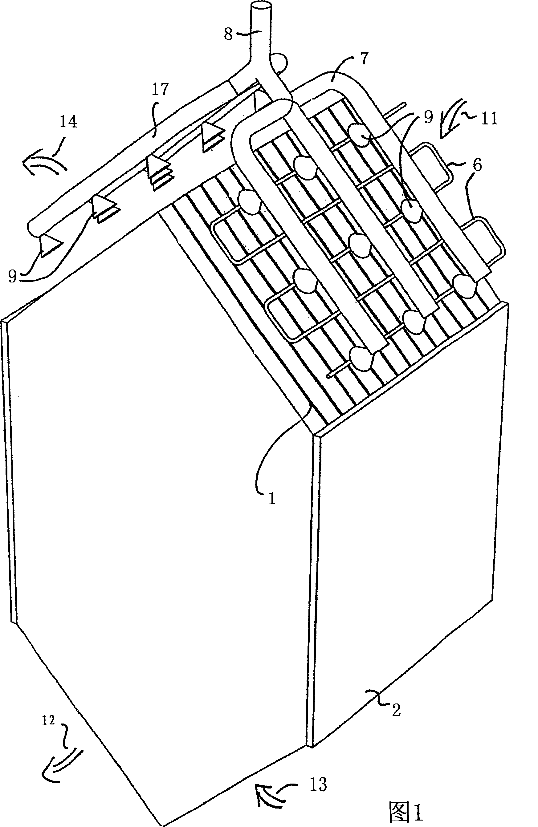
[0015] Figure 1 schematically shows a plate heat exchanger according to an exemplary embodiment of the present invention. The plate heat exchanger generally comprises a plurality of plates 1 arranged parallel to one another. The plate 1 forms a hexagonal shape, but any other shape can also be selected. The cavity created by the plate is shown in the figure 2 Among them, the reference number 2 represents the closed side wall placed opposite.

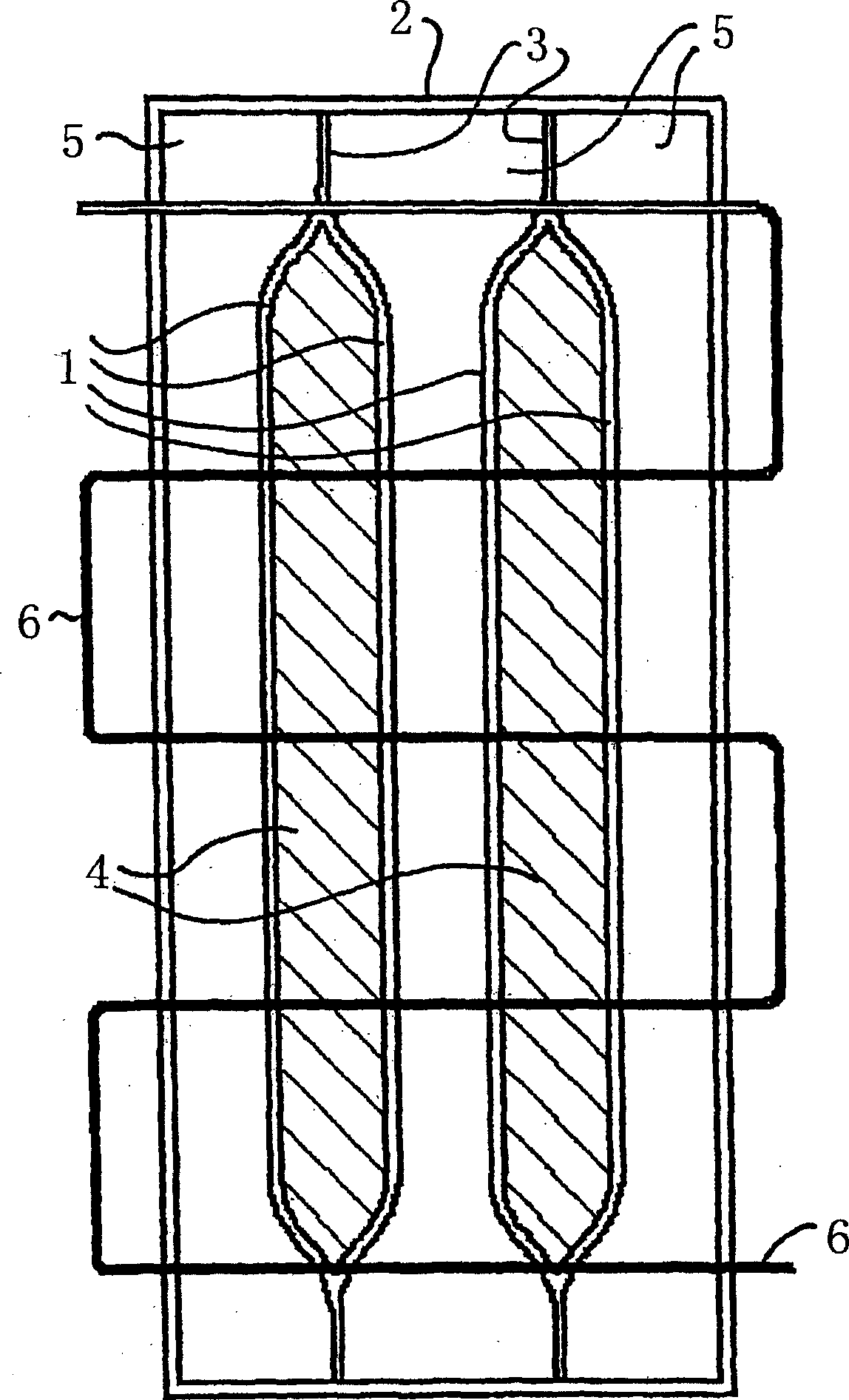
[0016] figure 2 A schematic partial view of the principle of a plate heat exchanger according to FIG. 1 is shown, with fewer plates 1 than shown in FIG. 1 . Between the side walls 2 , two pairs of plates 1 are welded together at their side end regions 3 and fastened to the outer wall 2 . Other configurations (such as glued joints) are also conceivable. This results in a cavity structure between the corresponding pair of plates 1, which are in figure 2 Marked by shading. These cavities denoted by reference numeral 4 can, for example...


PUM


Abstract

A plate heat exchanger for exchanging heat between a first air stream and a second air stream includes a plurality of plates limiting first and second exchange chambers which are serially arranged in a transversal direction with respect to the plates. A first air stream of outside air passes through the first exchange chambers, a second air stream originating from ventilated rooms passes through the second exchange chambers. The heat exchanger further includes an ionization device for ionizing particles entrained in the first air stream so that the particles deposit at conductive plates of the first exchange spaces, a water distribution system for periodically discharging water into the first exchange spaces for cleaning the plates of the heat exchanger from deposited particles, and a water collection device for discharging collected water.

Description

technical field [0001] The invention relates to a plate heat exchanger for exchanging heat between a first and a second gas flow, with a plurality of plates delimiting exchange chambers, said exchange chambers being alternated with respect to the transverse direction of said plates At intervals, a first airflow may flow through some exchange chambers and a second airflow may flow through the remaining exchange chambers, said second airflow containing exhaust air from the room to be ventilated via the exchange chambers of the heat exchanger , as exhaust gas to the outside of the room to be ventilated. Background technique [0002] Plate heat exchangers are well known in the prior art, by means of which heat energy is exchanged in ventilation systems. A disadvantage is that cooling the supplied fresh air or recirculating the room air usually requires energy-intensive devices in the architecture of an air-conditioning system or the like. [0003] Furthermore, air cleaning sys...

Claims


Application Information

Patent Timeline
IPC IPC(8): F28D5/00F24F5/00F24F12/00F28F19/01F28G1/16
CPCY02B30/16Y02B30/545F28G1/16F24F12/006F28D5/00F28F19/01Y02B30/563F24F5/0035Y02B30/54Y02B30/56
Inventor 乌尔斯·A·魏德曼
Owner MENTUS HLDG AG
Why Eureka
Try Eureka