
Transistor and strained channel element formation method

A technology of strained channels and transistors, which is applied in the manufacture of electrical components, semiconductor devices, semiconductor/solid-state devices, etc., to achieve the effect of reducing damage

Active Publication Date: 2006-04-19
TAIWAN SEMICON MFG CO LTD
View PDF0 Cites 6 Cited by
  • Summary
  • Abstract
  • Description
  • Claims
  • Application Information

AI Technical Summary

Problems solved by technology

[0011] The above-mentioned problems can be solved or prevented by the technical characteristics of the strained channel transistor with uncoordinated lattice regions proposed by the present invention.

Method used


Image

  • Transistor and strained channel element formation method
  • Transistor and strained channel element formation method
  • Transistor and strained channel element formation method

Examples


Embodiment Construction

[0034] The manufacturing method and using method of the preferred embodiment of the present invention will be disclosed below. The present invention provides an implementation concept, which can be applied in a wide range of implementation examples. The following disclosures are only methods for making and using certain embodiments of the present invention, and are not intended to limit the present invention.

[0035] The present invention relates to the field of semiconductor elements, in particular to a method for manufacturing stress channel field effect transistors with uncoordinated lattice regions. The manufacturing method of the first embodiment of the present invention will be disclosed below.

[0036] Figure 2a A substrate 100 is disclosed, having an active region 102 defined by a shallow trench isolation structure 101 . In addition, other types of isolation structures (such as LOCOS and mesa isolation structures) can be used to isolate the active region 102 . Su...


PUM


Abstract

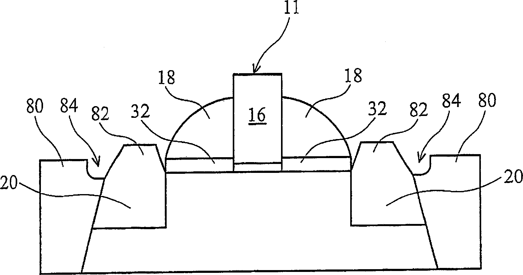
The invention provides a transistor and a method to form the strained channel transistor. The strained channel transistor comprises a substrate formed of a first material. A source region comprised of a second material is formed in a first recess in the substrate, and a drain region comprised of the second material is formed in a second recess in the substrate. A strained channel region formed of the first material is intermediate the source and drain region. A gate stack formed over the channel region includes a gate electrode overlying a gate dielectric. A gate spacer formed along a sidewall of the gate electrode overlies a portion of at least one of said source region and said drain region. A cap layer may be formed over the second material, and the source and drain regions may be silicided. The invention is a whole grid structure for preserving the strained channel transistor. Especially, it can avoid or reduce the damage of the grid structure.

Description

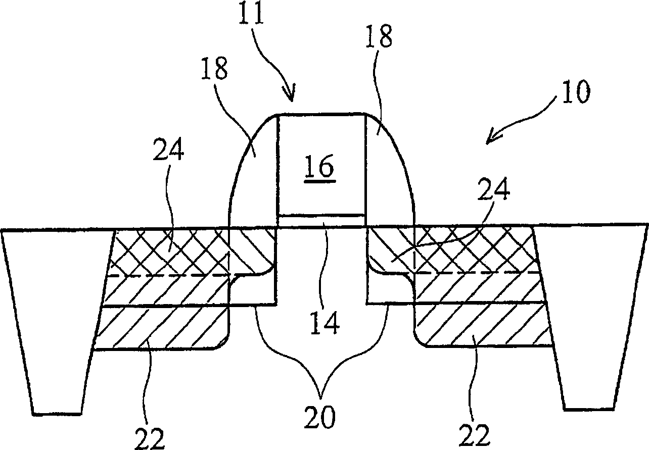
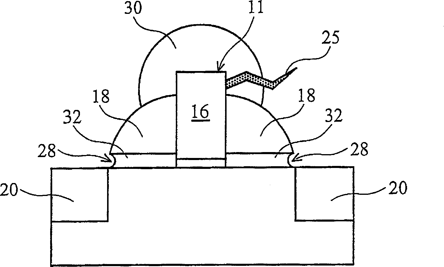
technical field [0001] The present invention relates to a semiconductor device, and more particularly to systems and methods for forming strained channel transistors. Background technique [0002] With demands for device scaling and low power, many developments have been made to improve electron mobility in the channel region of metal oxide semiconductor transistors. One of these developments involves creating strain in the channel region. It has been found that straining the channel region can improve the mobility of carriers in the channel region. The amount of strain directly affects (improves or reduces) the carrier mobility and the performance of the transistor. [0003] Figure 1a A perfect strained channel transistor 10 is shown. The strained channel transistor 10 includes a gate structure 11 having a gate dielectric layer 14 and a gate electrode 16 on the gate dielectric layer 14 . The gate structure 11 also includes spacers 18 along the gate 16 and the sidewalls...

Claims


Application Information

Patent Timeline
IPC IPC(8): H01L29/78H01L21/336
Inventor 黄怡君王焱平柯志欣
Owner TAIWAN SEMICON MFG CO LTD
Learn More