Oscillator starting control circuit
A start-up control and oscillator technology, which is applied to power oscillators, electrical components, generator start-ups, etc., can solve problems such as inability to output oscillation frequency, shorten start-up time, increase power consumption, and stabilize start-up time Effect
- Summary
- Abstract
- Description
- Claims
- Application Information
AI Technical Summary
Problems solved by technology
Method used
Image
Examples
no. 1 approach
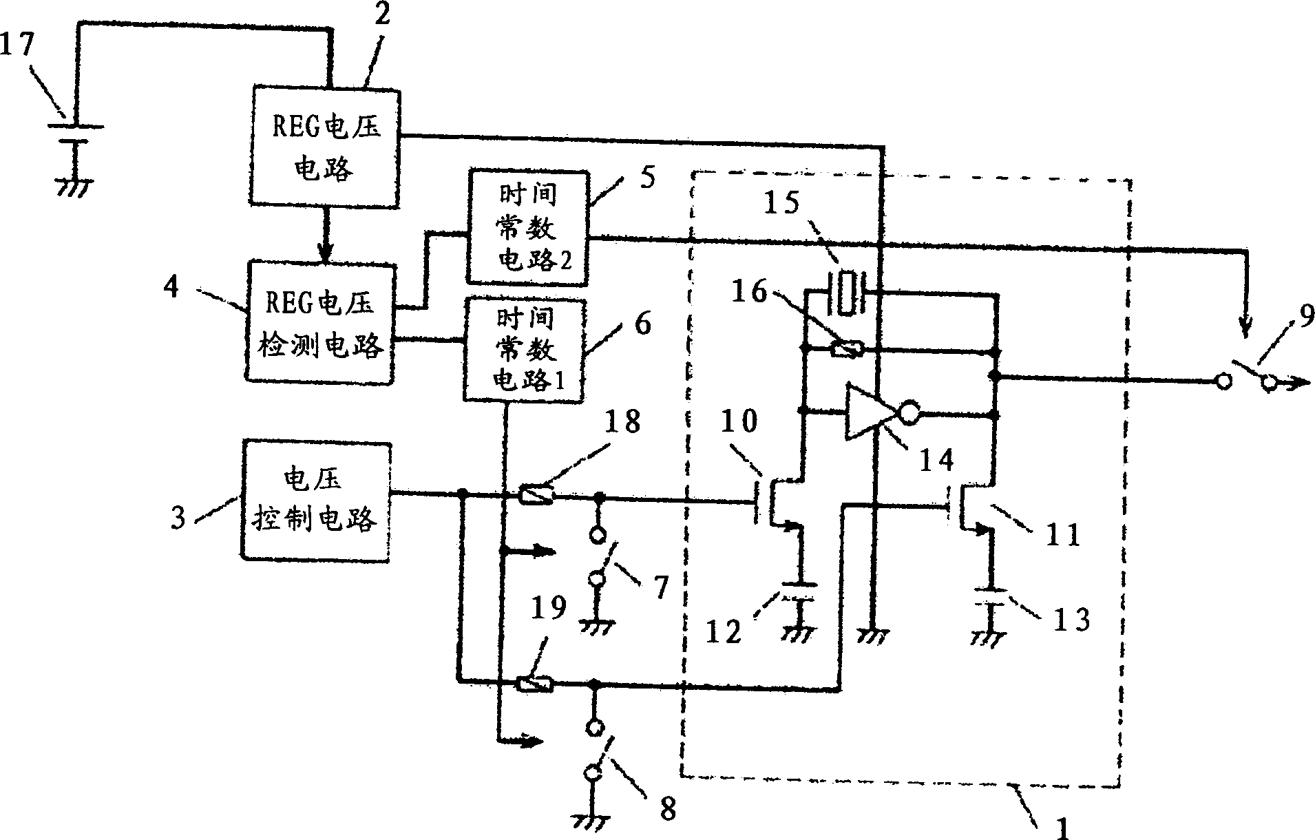
[0053] figure 1 It is a figure which shows the 1st Embodiment of the oscillator start-up control circuit of this invention.
[0054] exist figure 1 Among them, the REG voltage is applied to the oscillation circuit (1: oscillator) through the REG voltage circuit (2) to which the power supply voltage (17) is applied. figure 1 The oscillating circuit (1) is a crystal oscillating circuit as follows: the input and output of the inverter (14) are connected to the two ends of the crystal oscillator (15) and the two ends of the resistor (16), and the input is connected to the MOS. The drain of the variable capacitor (10), the output is connected to the drain of the MOS variable capacitor (11), the source of the MOS variable capacitor (10) is connected to the fixed capacitor (12), and the MOS variable capacitor (11 ) is connected to a fixed capacitor (13), and the other end of the fixed capacitor (12, 13) is connected to GND.
[0055] Furthermore, a resistor (18) and a switch (7:...
no. 2 approach
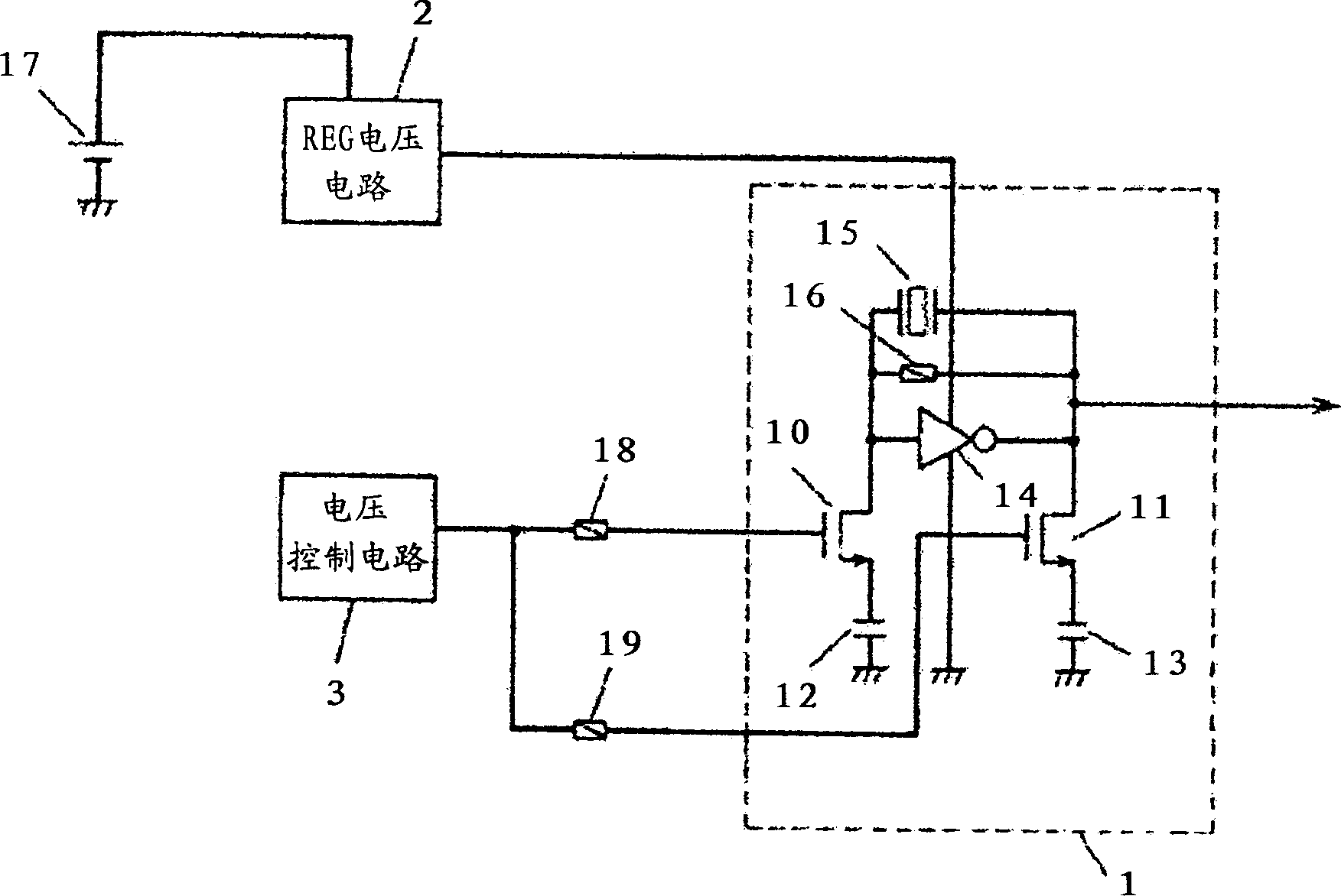
[0073] Figure 9 It is a diagram showing a second embodiment of an oscillator activation control circuit different from the first embodiment in the shape of a variable capacitance element (10) and the method of applying a voltage from a voltage control circuit (3, 22).
[0074] exist Figure 9 Among them, the REG voltage is applied to the oscillation circuit (1) through the REG voltage circuit (2) to which the power supply voltage (17) is applied. Figure 9 The oscillating circuit (1) is the following crystal oscillating circuit: the input and output of the inverter (14) are connected to the two ends of the crystal oscillator (15) and the two ends of the resistor (16), and then the input and output are connected to Capacitors (20), (21) for cutting off the control voltage applied to the MOS variable capacitor (10), the gate of the MOS variable capacitor (10) is connected to the first control voltage circuit (3), and the drain Connect to the second control voltage circuit (22...
no. 3 approach
[0080] Figure 10 It means that in order to improve the stability of the oscillation frequency after start-up, during a certain period of time generated by the time constant circuit 1 (6), the floating node is fixed by the switch (24) of the variable capacitance element (10). It is a diagram of the third embodiment in which the node is stabilized to an oscillating stable voltage, and the floating node is returned to the normal floating state after the above-mentioned certain period of time.
[0081] Figure 10 The oscillator circuit (1) is in Figure 9 The source of the MOS variable capacitor (10) of the oscillating circuit (1) is connected to the resistor (23) and the switch (24: the third switch), and the other end of the resistor (23) is connected to the third control voltage circuit (25) Crystal oscillator circuit.
[0082] On the other hand, the REG voltage detection circuit (4) is connected to transmit a signal for detecting the rise of the REG voltage circuit (2), an...
PUM
 Abstract
Description
Claims
Application Information
 - R&D
- Intellectual Property
- Life Sciences
- Materials
- Tech Scout
- Unparalleled Data Quality
- Higher Quality Content
- 60% Fewer Hallucinations
Browse by: Latest US Patents, China's latest patents, Technical Efficacy Thesaurus, Application Domain, Technology Topic, Popular Technical Reports.
© 2025 PatSnap. All rights reserved.Legal|Privacy policy|Modern Slavery Act Transparency Statement|Sitemap|About US| Contact US: help@patsnap.com


