
Waste gas purifier

A technology of exhaust gas purification device and adsorption device, which is applied in chemical instruments and methods, separation of dispersed particles, separation methods, etc., can solve the problems of reducing organic waste gas content, clogging of dust adsorption beds, pollution, etc., to achieve thorough gas purification and reduce emissions volume effect

Inactive Publication Date: 2006-04-26
王阿青
View PDF0 Cites 3 Cited by
  • Summary
  • Abstract
  • Description
  • Claims
  • Application Information

AI Technical Summary

Problems solved by technology

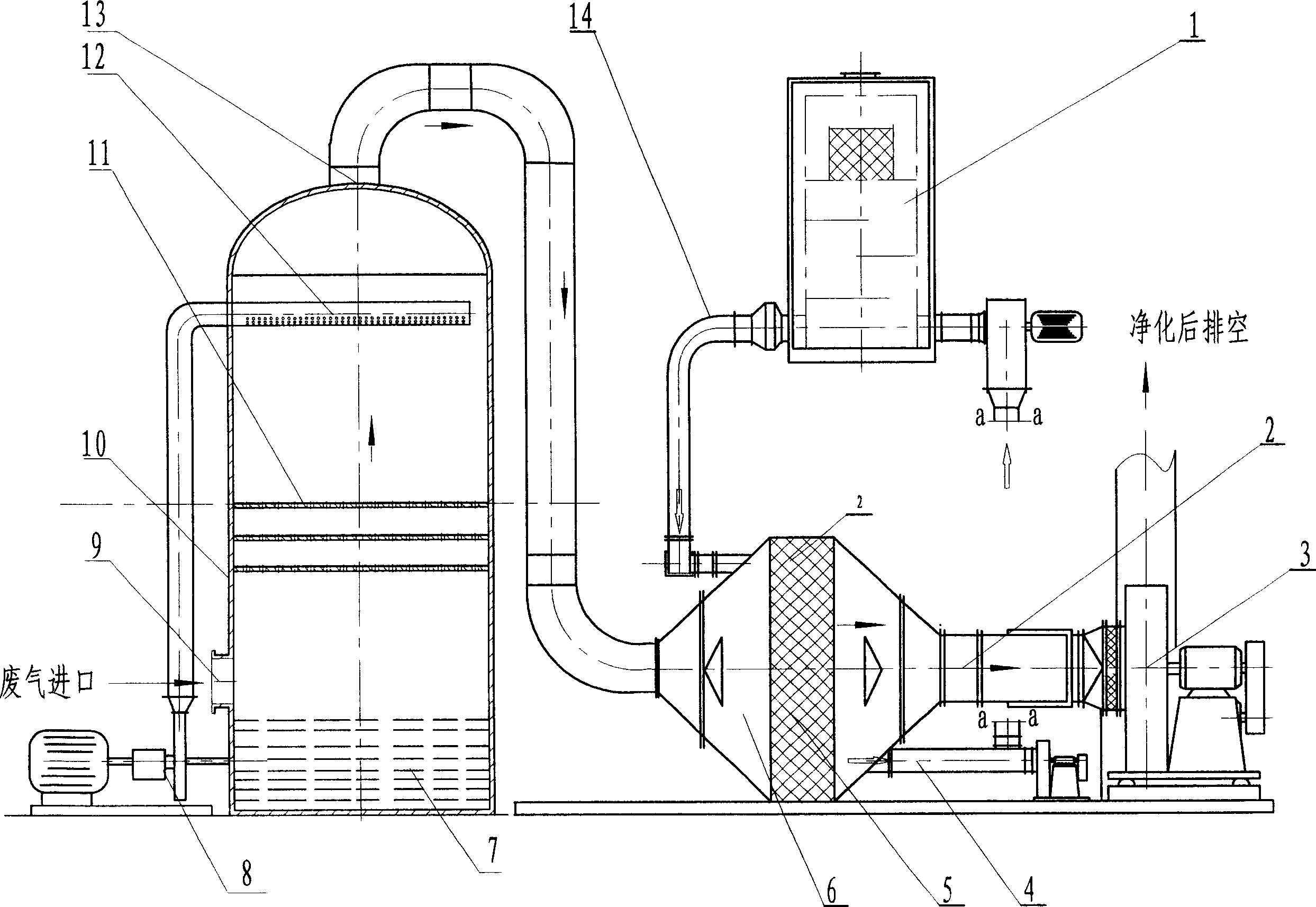
When in use, the waste gas that needs to be treated is passed into the device from the air inlet of the adsorption device. After the waste gas is absorbed by activated carbon, the content of organic waste gas in it is effectively reduced. The air valve can be opened to start the main fan to discharge to the outside. When the bed reaches or is about to reach saturation, stop the adsorption operation, close the air valve, and blow the adsorption bed from the inlet side of the adsorption bed with the hot airflow generated by the catalytic purification device to desorb the adsorbate. At the same time, the activated carbon adsorption bed is regenerated and desorbed. The attached organic matter has been concentrated and sent to the catalytic purification device through the bypass branch, where it is catalytically combusted in the catalytic purification device to generate CO 2 and H 2 O discharge, when the concentration of organic waste gas reaches 2000ppm, it can maintain combustion in the catalytic purification device without external heating, otherwise, it needs to burn oil, liquefied gas, coal, etc. for auxiliary combustion, and most of the exhaust gas after combustion is sent to the adsorption bed , used for desorption and regeneration of activated carbon; the regenerated adsorption bed can be used repeatedly for adsorption; its disadvantage is that some gases and dust cannot be burned, but they are also directly discharged to the atmosphere during the work process to cause pollution. At the same time, the dust It is also easy to cause the clogging of the adsorption bed.

Method used


Image

  • Waste gas purifier

Examples


Embodiment Construction

[0009] As shown in the figure, a waste gas purification device includes an adsorption device 6, the adsorption device 6 is provided with an air inlet and an air outlet, and an activated carbon adsorption bed 5 is arranged between the air inlet and the air outlet of the adsorption device 6, and the adsorption device 6 Also be provided with a bypass branch 4 on the exhaust side of the adsorption bed 5, the bypass branch 4 is connected to the catalytic purification device 1 through the fan, the outlet 14 of the catalytic purification device is connected to the intake side of the adsorption bed 5, and the adsorption The outlet of the device 6 is connected with a damper 2, the outlet of the damper 2 is connected to the inlet of the main fan 3 through a connecting pipe, the outlet of the main fan 3 is connected to the atmosphere, and the inlet of the adsorption device 6 is connected to the waste gas outlet 13 of an absorption device, the absorption device includes an upright The clos...


PUM


Abstract

The invention discloses an exhaust purification device in environmental protection field, which comprises: an adsorption device with an active carbon adsorption bed arranged between inlet and outlet of the device, arranging a bypass branch connected with a catalysis cleaning device by a fan on exhaust side of the said bed; connecting the outlet of catalysis cleaning device to inlet side of said bed; connecting the outlet of adsorption device to inlet of fan by air-valve; connecting the fan outlet to air; linking the inlet of adsorption device to one exhaust-gas outlet of absorption device that comprises a stand closed tower body with circulation pool on bottom connected to circulation pump inlet; connecting the outlet of said pump to liquid distributor on tower upper with some holes; arranging a water-curtain device in tower body under said distributor; arranging inlet and outlet for exhaust gas on side and top of the tower body. This invention can reduce the discharge of dust and harmful gas.

Description

technical field [0001] The invention relates to an environmental protection device, in particular to a gas purification device. Background technique [0002] In the existing industrial production process, especially in the process of paint processing and operation, various waste gases are often produced. These waste gases contain inorganic waste gas, organic waste gas and dust, etc. If they are directly discharged into the air, it will cause air pollution. Therefore, the waste gas must be treated before it can be discharged; currently there is a waste gas purification device, including an adsorption device, the adsorption device is provided with an air inlet and an air outlet, and an activated carbon is arranged between the air inlet and the air outlet of the adsorption device. Adsorption bed, the adsorption device is located on the exhaust side of the adsorption bed and also has a bypass branch, the bypass branch is connected to the catalytic purification device through the...

Claims


Application Information

Patent Timeline
IPC IPC(8): B01D53/18
Inventor 王阿青
Owner 王阿青
Learn More