Plasma waste gas treatment device and method

A waste gas treatment device and plasma technology, which is applied in separation methods, chemical instruments and methods, and dispersed particle separation, can solve the problems of limited perfluoride treatment capacity and low efficiency, and achieve the protection of follow-up equipment and gas-liquid mass transfer. full, responsive effect

Active Publication Date: 2019-05-31
上海高笙集成电路设备有限公司
View PDF9 Cites 10 Cited by
  • Summary
  • Abstract
  • Description
  • Claims
  • Application Information

AI Technical Summary

Problems solved by technology

The dry adsorption method adopts adsorbent adsorption, and the efficiency is low; the wet cleaning method is only suitable for gases that are easily soluble in water; 3 This kind of unstable fluoride; the temperature of the combustion wet cleaning method can reach 1600 °C, and it can handle some perfluorinated compounds. The ability to deal with perfluorinated compounds with a very stable molecular structure is limited, and the combustion wet cleaning method needs to pass CH 4 、C 3 h 8 and O 2 After combustion, the greenhouse effect gas CO will be produced. 2

Method used


Image

  • Plasma waste gas treatment device and method
  • Plasma waste gas treatment device and method
  • Plasma waste gas treatment device and method

Examples


Embodiment 1

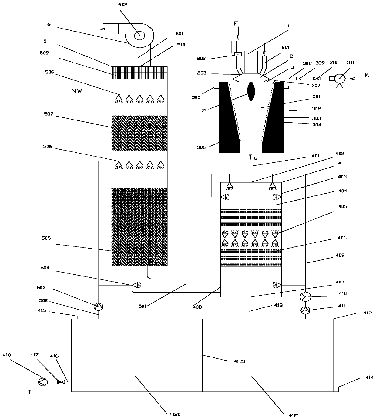
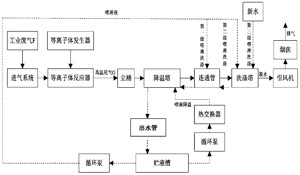
[0080] see figure 1 As shown, a plasma treatment waste gas device for implementing the method includes a thermal reaction system, an air intake system, a cooling system, a multi-stage purification and washing system, and an exhaust system. in:

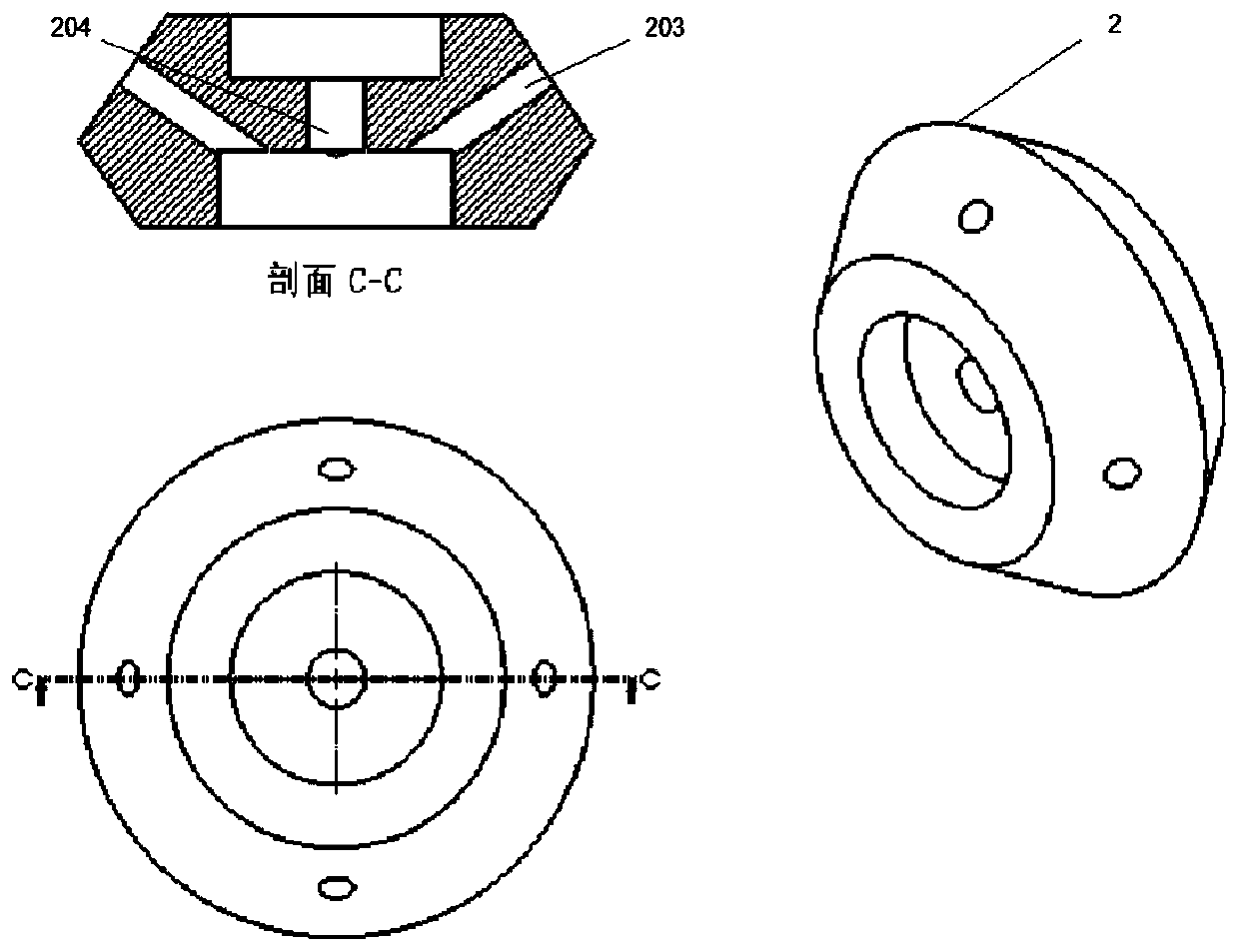
[0081] The thermal reaction system includes a plasma generator 1 as a heat source and a plasma reactor 3 . The plasma generator 1 is installed at the center of the upper concave surface of an air inlet device 2 , and the air inlet device 2 is arranged at the center of the top of the plasma reactor 3 . The plasma reactor 3 comprises a housing 302, a funnel-shaped pyrolysis reaction chamber 301 of a hollow structure and a circulating water cooling chamber 306 arranged on the outer layer of the pyrolysis reaction chamber 301, and the two chambers are composed of a layer The bucket wall 302 is separated, and the inner bucket wall formed by the microporous plate 303 is also installed on the inside of the bucket wall 302. There is a sealed...

Embodiment 2

[0106] combine figure 1with figure 2 As shown, a method for plasma treatment of exhaust gas, comprising the following steps:

[0107] (1) The plasma generator 1 generates a thermal plasma jet (plasma torch) under the action of an external electric field, and injects it into the pyrolysis reaction chamber 301 of the plasma reactor 3, and passes the industrial waste gas F to be treated through a group of intake pipes 201 It is introduced into the pyrolysis reaction chamber 301 of the plasma reactor 3 through a corresponding set of cyclone nozzles 203, and undergoes high-temperature cracking and purification treatment to rapidly decompose or oxidize the industrial waste gas F and turn it into a harmless product or a substance that is easy to handle , this step is the core of the whole set of purification technology. The basic principle of the reaction is that the plasma generator generates high-energy active particles under the action of an electric field, and these high-energ...


PUM


Abstract

The invention provides a plasma waste gas treatment device and method, and belongs to the technical field of waste gas treatment.The plasma waste gas treatment device comprises a thermal reaction system, an air inlet system, a cooling system, a multistage purification washing system, an exhaust system and a liquid circulating system, and the structureis compact, safe and reliable.The plasma wastegas treatment method comprises the following steps of: carrying out high-temperature cracking reaction after waste gas to be treated enters into the thermal reaction system through the air inlet system, and carrying out quenching and preliminary purification after entering the cooling system; carrying out washing and purification for a plurality of times after entering the multistage washing system; finally discharging the waste gas from a chimney through a dehydration layer under the action of an induced draft fan.The waste gas is subjected to high-temperature cracking, cooling, preliminary purification and multistage purification, so that the purification speed is obviously improved; and the waste gas which can be treated by the method comprises perfluorides, inflammable substances, corrosion, poisons and the like, the purification is thorough, the method is safe and reliable.

Description

technical field [0001] The invention relates to the technical field of waste gas treatment, in particular to a plasma waste gas treatment device and method. Background technique [0002] The development of the integrated circuit industry has risen to a national strategy, which is related to national defense technology, national security and other aspects of the national economy and people's livelihood. With the rapid growth of the integrated circuit industry, the hidden industrial pollution problem has also been paid more and more attention. A large amount of flammable, corrosive or highly toxic chemical raw materials must be used in the integrated circuit manufacturing process, and the utilization rate of chemical raw materials in the integrated circuit manufacturing process is set at a very low ratio. In this way, incompletely reacted residual chemical raw materials, reaction by-products, and harmful steam evaporated from the raw material tank during the integrated circui...

Claims


Application Information

Patent Timeline
Patent Type & Authority Applications(China)
IPC IPC(8): B01D53/32B01D53/18B01D47/06
CPCY02P70/10
Inventor 郑煜蒋连琼吴雄辉何浩吴瑶刘志杰段吉安
Owner 上海高笙集成电路设备有限公司
Why Eureka
Try Eureka