Backing plates for sputtering targets

A technology of backing plate and sputtering target, which is applied in the field of backing plate for sputtering target, which can solve the problems of increased cost, failure to prevent cracking of brazing material, insufficient combination of target and backing plate, etc., to reduce cracking , save the effect of leveling treatment

Inactive Publication Date: 2006-04-26
KOBELCO RES INST
View PDF3 Cites 5 Cited by
  • Summary
  • Abstract
  • Description
  • Claims
  • Application Information

AI Technical Summary

Problems solved by technology

According to this technique, the combination of target and backing plate does not sufficiently and reliably reduce the difference in coefficient of thermal expansion, and does

Method used


Image

  • Backing plates for sputtering targets
  • Backing plates for sputtering targets
  • Backing plates for sputtering targets

Examples


Example Embodiment

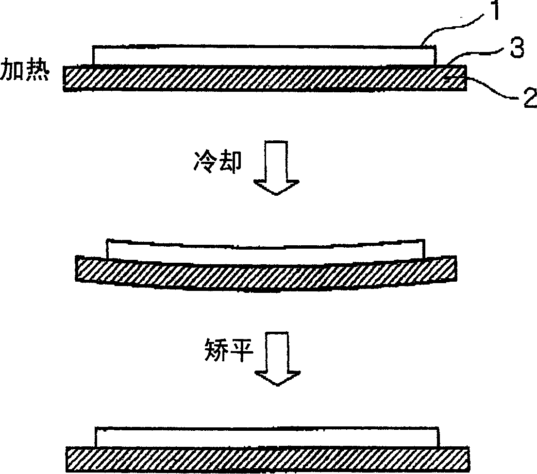
[0021] The inventors of the present invention have conducted a detailed study on a backing plate for a sputtering target. The backing plate reduces the warpage that occurs when combined with the target and the film deposition (sputtering) of the Al-Nd alloy thin film. Stress, eliminating the warpage and leveling, reducing the cracking of the brazing material placed between the target and the backing plate caused by repeated warpage formation and leveling, and thus enabling long-term stable film deposition operations . In particular, they conducted detailed studies on backing plates for sputtering targets, which reduce warpage even when the target contains Al alloys such as Al- In the case of Nd, Al-Ti and Al-Ta alloys, or metals such as Mo, Ta, and Ti, leveling is also omitted and film deposition can be repeated.
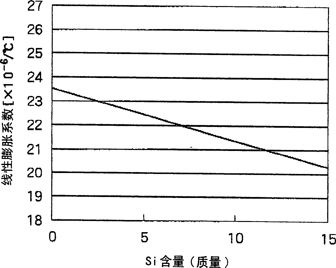
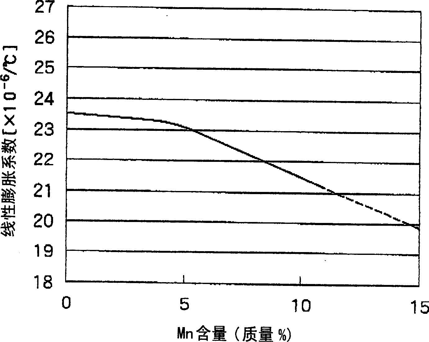
[0022] Therefore, they found that the best backing plate for sputtering targets contains an average linear expansion coefficient of 23.0×10 at a temperature of 25°C to ...


PUM


Abstract

A backing plate for a sputtering target includes an aluminum alloy having an average linear expansion coefficient of 23.0×10⁻⁶/°C or less at a temperature of 25°C to 100°C. This kind of backing plate prevents the warpage that occurs when it is combined with the target, reduces the stress that occurs during the film deposition (sputtering) of the Al-Nd alloy film, saves the warpage leveling treatment, and reduces the installation time. Fracture of the brazing material between the target and the backing plate enables a stable film deposition operation over a long period of time.

Description

technical field [0001] The present invention relates to a backing plate for a sputtering target. Specifically, it relates to a backing plate for a sputtering target, which prevents warpage during bonding with the target and / or film deposition (sputtering) of an Al-Nd alloy thin film, and enables long-term stable film deposition operations. Background technique [0002] Sputtering is commonly used to make the thin films that make up liquid crystal panels and organic electroluminescent (EL) panels used in televisions, laptops, and other monitors , and to fabricate interconnect films for optical recording and semiconductor fields. In the sputtering method, a plasma discharge is induced between a substrate and a target serving as a film material, the gas ionized by the plasma discharge collides with the target, thereby knocking atoms out of the target, and these atoms are deposited on the substrate to produce thin films. Compared with vacuum vapor deposition and arc ion plat...

Claims


Application Information

Patent Timeline
IPC IPC(8): C23C14/34
CPCC23C14/3407H01J37/3435C22C21/02C23C14/14
Inventor 茂山和基森元荣一
Owner KOBELCO RES INST
Why Eureka
Try Eureka