Cathode structure for inversion type organic luminous assembly

A technology of light-emitting components and cathode structures, applied in the direction of light-emitting materials, electroluminescent light sources, light sources, etc., can solve the problems of easy diffusion, easy reaction and deterioration, and difficult use and processing of highly active metals

Inactive Publication Date: 2006-04-26
IND TECH RES INST
View PDF0 Cites 4 Cited by
  • Summary
  • Abstract
  • Description
  • Claims
  • Application Information

AI Technical Summary

Problems solved by technology

However, the electron injection layer in the cathode structure of this component is doped with low work function and high activity metals in the organic material layer as n-type conductive doping, because there are still difficulties in dealing with low work function and high activity metals in the process of this component In addition, according to reports, metal atoms such as lithium (Li) and cesium (Cs) are prone to diffusion problems in organic materials, which will affect the operation of components
[0008] Generally speaking, in the past literatures on inverted structure organic light-emitting components, the lower electrode cathode structure and manufacturing process contain low work function and high-activity metals, which are easy to react and deteriorate and affect the characteristics of components. On the other hand, in the current manufacturing of organic light-emitting displays It is still quite difficult to deal with the application of highly reactive metals

Method used


Image

  • Cathode structure for inversion type organic luminous assembly
  • Cathode structure for inversion type organic luminous assembly
  • Cathode structure for inversion type organic luminous assembly

Examples


Embodiment 1

[0076] In order to illustrate that the use of the electron injection layer of the present invention can effectively improve the electron injection capability of an organic light-emitting device with an inverted structure using silver (Ag) as the cathode conductive metal, a dual-cathode electronic single-carrier device was fabricated for comparison.

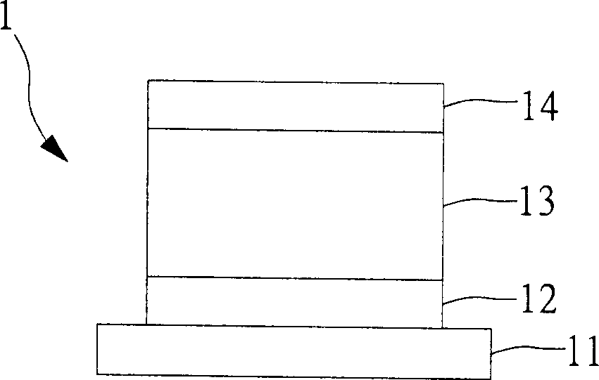
[0077] In this embodiment, please refer to the structure of component A Figure 4A , wherein the substrate 41 is a glass substrate, the lower electrode cathode layer 42 is 80 nanometers thick silver (Ag), and the organic electron transport layer 43 is 80 nanometers thick Alq 3 , the upper electrode cathode layer 44 is 0.5 nanometer thick lithium fluoride (LiF) / 100 nanometer thick aluminum (Al).

[0078] For the structure of component B, please refer to Figure 4B , wherein the substrate 51 is a glass substrate, the lower electrode cathode layer 52 is 80 nanometers thick silver (Ag), and the electron injection layer 53 is 0.2 nano...

Embodiment 2

[0082] In order to illustrate that the use of the electron injection layer of the present invention can effectively improve the electron injection capability of an organic light-emitting device with an inverted structure using aluminum (Al) as the cathode conductive metal, a dual-cathode electronic single-carrier device was fabricated for comparison.

[0083] In this embodiment, please refer to the structure of component C Figure 5A , wherein the substrate 61 is a glass substrate, the lower electrode cathode layer 62 is 80 nanometers thick silver (Ag), and the organic electron transport layer 63 is 80 nanometers thick Alq 3 , the upper electrode cathode layer 64 is 0.5 nanometer thick lithium fluoride (LiF) / 100 nanometer thick aluminum (Al).

[0084] Please refer to B of the figure for the structure of component D, wherein the substrate 71 is a glass substrate, the lower electrode cathode layer 72 is silver (Ag) with a thickness of 80 nanometers, and the electron injection la...

Embodiment 3

[0088] In this embodiment, in order to illustrate the influence of the electron injection layer of the present invention on the photoelectric characteristics of an organic light-emitting component with an inverted structure using silver (Ag) as the cathode of the lower electrode, the following components were fabricated for comparison:

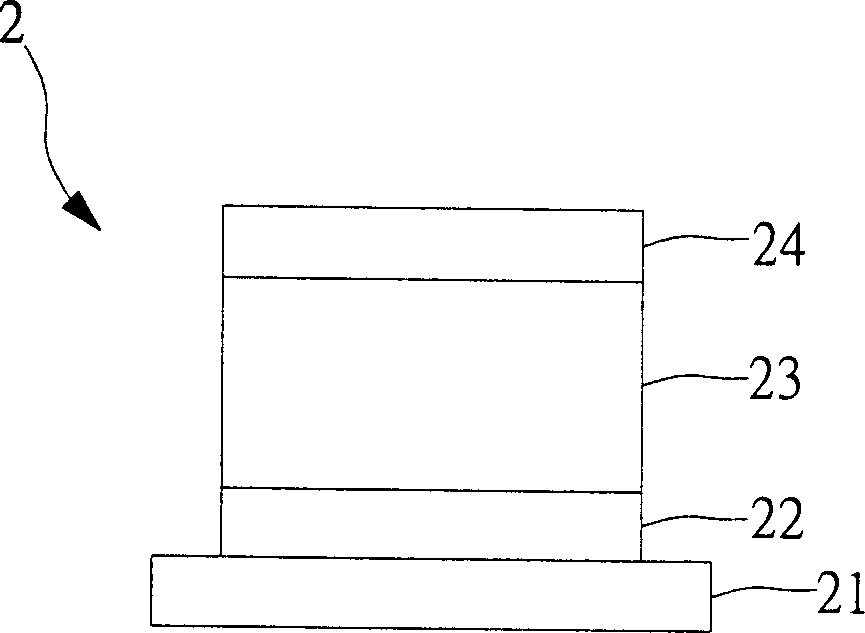
[0089] In this embodiment, the structure of component E can refer to Figure 2A , wherein the substrate 21 is a glass substrate, the cathode layer 22 is 80 nanometers thick silver (Ag), and the organic structure layer 23 is 50 nanometers thick Alq 3 / 40 nm thick α-NPD / 20 nm thick m-MTDATA and F 4 -TCNQ mixture, the anode layer 24 is 20 nanometers thick silver (Ag), and the outermost layer is provided with a 30 nanometers thick tellurium oxide (TeO 2 ) as a refractive index matching layer.

[0090] For the structure of component F, please refer to image 3 , wherein the substrate 31 is a glass substrate, the cathode layer 32 is 80 nanometers ...


PUM


Abstract

The cathode structure used to inverted organic light-emitting assembly comprises from bottom to top, a conductive electrode layer, an organic material layer, a dielectric material layer, and a metal plate. This invention can avoid using metal with low power function and high activity, and benefit to the manufacture and environmental stability.

Description

technical field [0001] The present invention relates to a cathode structure for an inverted organic light-emitting component, in particular to a cathode structure for an inverted organic light-emitting component provided with an electron injection layer. Background technique [0002] Over the past ten years, the research and development of organic conductive molecules and polymer materials has been extremely rapid. With the availability of organic conductors, insulators, and semiconductor materials, organic semiconductor materials have been used in the fields of electronics and optoelectronic components, such as organic thin film light-emitting diodes ( Organic light-emitting diodes), organic lasers (organic lasers), organic memory elements (organic memory), solar cells (solar cells), and thin film transistors (thin film transistors, TFTs), etc., are gradually showing practical potential. Generally speaking, organic semiconductor optoelectronic components have the characteri...

Claims


Application Information

Patent Timeline
Patent Type & Authority Applications(China)
IPC IPC(8): H05B33/20C09K11/06H05B33/12H05B33/26
Inventor 叶永辉吴忠帜陈介伟林俊良杨志仁
Owner IND TECH RES INST
Why Eureka
Try Eureka