
Material disperser

A batching machine and material technology, applied in mixers, mixers with rotary stirring devices, dissolving and other directions, can solve the problems of inability to adjust particle thickness, rapid wear of rotors and stators, and high operating costs, and achieve stable and uniform production results. The effect of improving industrial production efficiency and reducing production costs

Inactive Publication Date: 2006-05-10
韩飞
View PDF0 Cites 4 Cited by
  • Summary
  • Abstract
  • Description
  • Claims
  • Application Information

AI Technical Summary

Problems solved by technology

The machine has the following disadvantages: a. The stirring speed is slow and the time is long; b. It is easy to agglomerate and form a dough; c. The stirring is uneven; d. The condensate is accumulated or adsorbed on the container tank, tank wall or internal joint fittings
This process has the following disadvantages: a. The rotor and stator wear quickly, and usually a set of rotor and stator has to be replaced every six months to one year; b. The processing capacity is small and the speed is slow; c. Loud noise; d. High energy consumption; e .Only suitable for low viscosity, low concentration products
But its shortcomings are very prominent: a. Its fixed cylindrical strong screen is easy to block, so it can only be applied to products with low viscosity and low concentration, and it cannot be applied when the concentration and viscosity of the product are high; b. Often in the system There are dead corners and residues that are not easy to clean; c. Single function, no crushing and emulsifying functions; d. Cannot adjust the thickness of particles; e. Small processing capacity, only suitable for small and medium-sized production requirements
[0006] 4. Gear pump type, this structure is suitable for high-viscosity products, but not for low-viscosity products; the equipment has slow speed and small processing capacity, and is suitable for small-scale production requirements; the system is expensive and costly; accessories Many, complex maintenance, high operating costs; the system has a single function, no crushing function

Method used

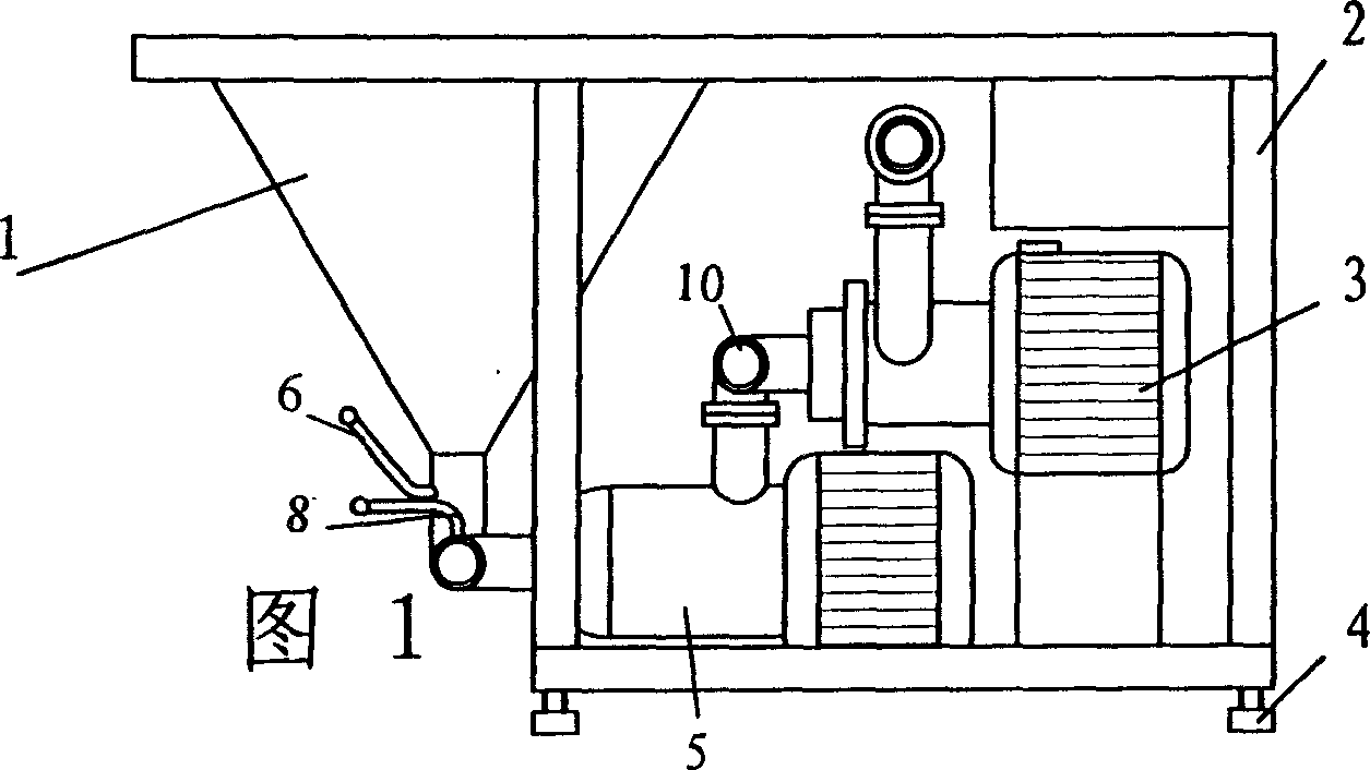
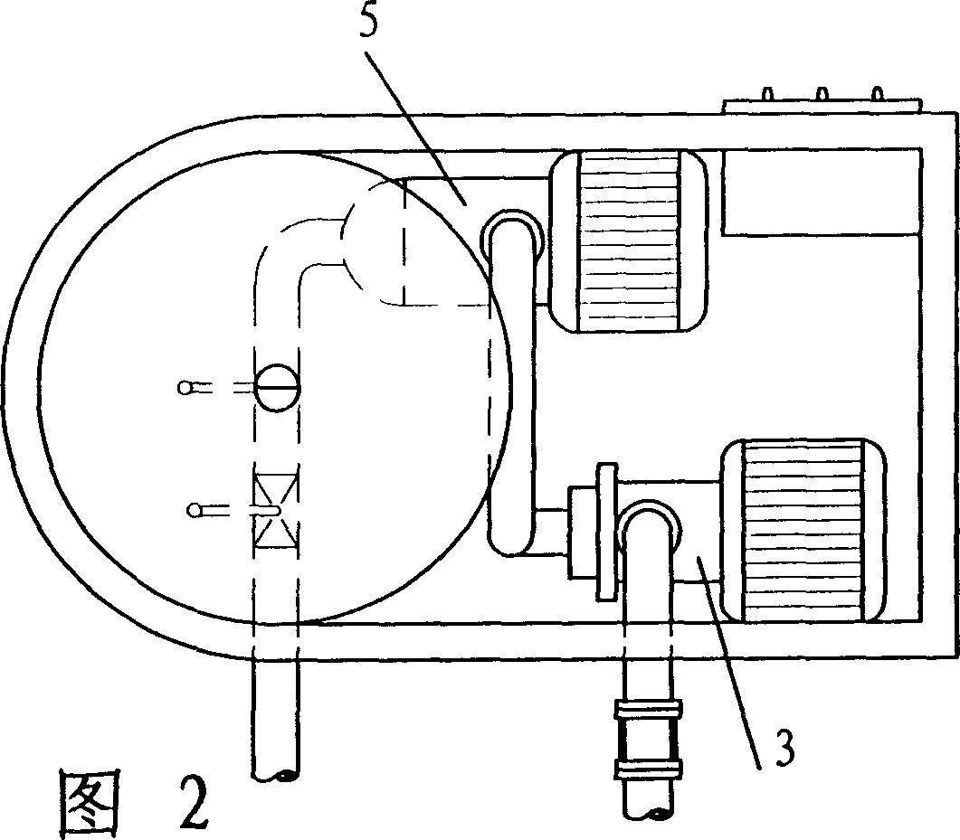
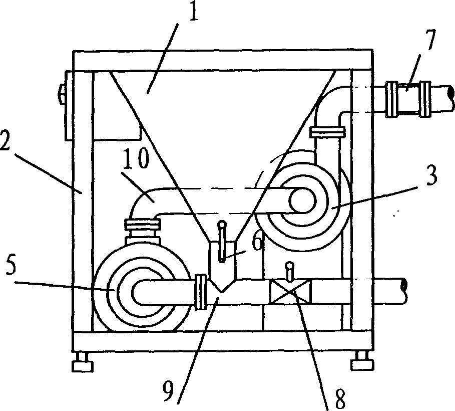

Image

  • Material disperser
  • Material disperser
  • Material disperser

Examples


Embodiment Construction

[0035] See Figure 1, Figure 2 and image 3 , the material batching machine of the present invention comprises a cabinet 2, a self-priming pump 5 driven by a motor installed at the bottom of the cabinet, and a pump connected to the feed pipe 9 of the self-priming pump and fixedly installed on the top surface of the cabinet 2 The solid hopper 1 is connected to the self-priming pump 5 through the channel 10, and the motor-driven mixing and crushing device 3 is provided with control valves 6 and 8 at the outlet of the solid hopper 1 and the inlet of the self-priming pump, respectively.

[0036] The self-priming pump is a self-priming sanitary delivery pump (commercially available), which is an important part of the machine and provides power for the solid material system, especially in the production of high-viscosity material products, the self-priming pump with strong suction Pumps are indispensable. The self-priming pump ensures the correct flow direction of the liquid and the ...


PUM


Abstract

The invention relates to a material distributor, which comprises a cabinet, a self-sucking pump mounted on the bottom of cabinet and driven by motor, a solid charging hopper through with the charging pipe of self-sucking pump and mounted on the top surface of cabinet, a mixed crush device connected to self-sucking pump via channel and driven by motor, and two control valves are mounted on the outlet of solid charging hopper and the inlet of self-sucking pump. The invention can used in the areas of pharmacy, foodstuff, drinking, cosmetic and paper making which need high effect mixing of solid-liquid and liquid-liquid, and it can apply variable low and high viscosity product, while the attained product has stable quality. And it has the functions of mixing, diffusing, emulsifying, and diffusing groups. The inventive device has reliable structure, lower energy-consumption, high producing efficiency, and reduced producing cost.

Description

technical field [0001] The invention relates to equipment for processing materials in industrial production, in particular to a material batching machine. Background technique [0002] Over the years, in the fields of food, medicine and chemical industry, the batching and processing equipment of materials mainly include: [0003] 1. Large tank or container mixing-mixer, which occupies a dominant position in the current industrial production practice. Put the solid ingredients together with the liquid ingredients into a large pot or container and stir with a mixer until the coagulum is completely dispersed in the ingredients. Depending on the amount of mixture and the concentration of the thickener, the time required for this process varies, but at least 40-150 minutes. This machine has the following disadvantages: a. slow stirring speed and long time; b. easy to agglomerate and form dough; c. uneven stirring; d. condensation accumulation or adsorption on the container tank...

Claims


Application Information

Patent Timeline
Patent Type & Authority Applications(China)
IPC IPC(8): B01F7/16
Inventor 韩飞
Owner 韩飞
Learn More