
Etching method and method for manufacturing thin film transistor employing the same

A technology of thin film transistor and manufacturing method, which is applied in semiconductor/solid state device manufacturing, electrical components, circuits, etc., can solve the problems of residue, abnormal display of liquid crystal display, slow etching rate, etc., and achieve the effect of high pass rate

Inactive Publication Date: 2006-05-10
CHUNGHWA PICTURE TUBES LTD
View PDF0 Cites 4 Cited by
  • Summary
  • Abstract
  • Description
  • Claims
  • Application Information

AI Technical Summary

Problems solved by technology

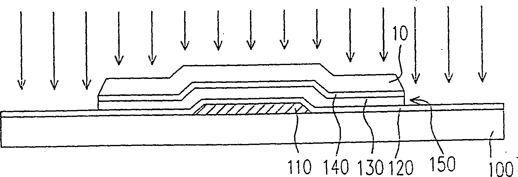
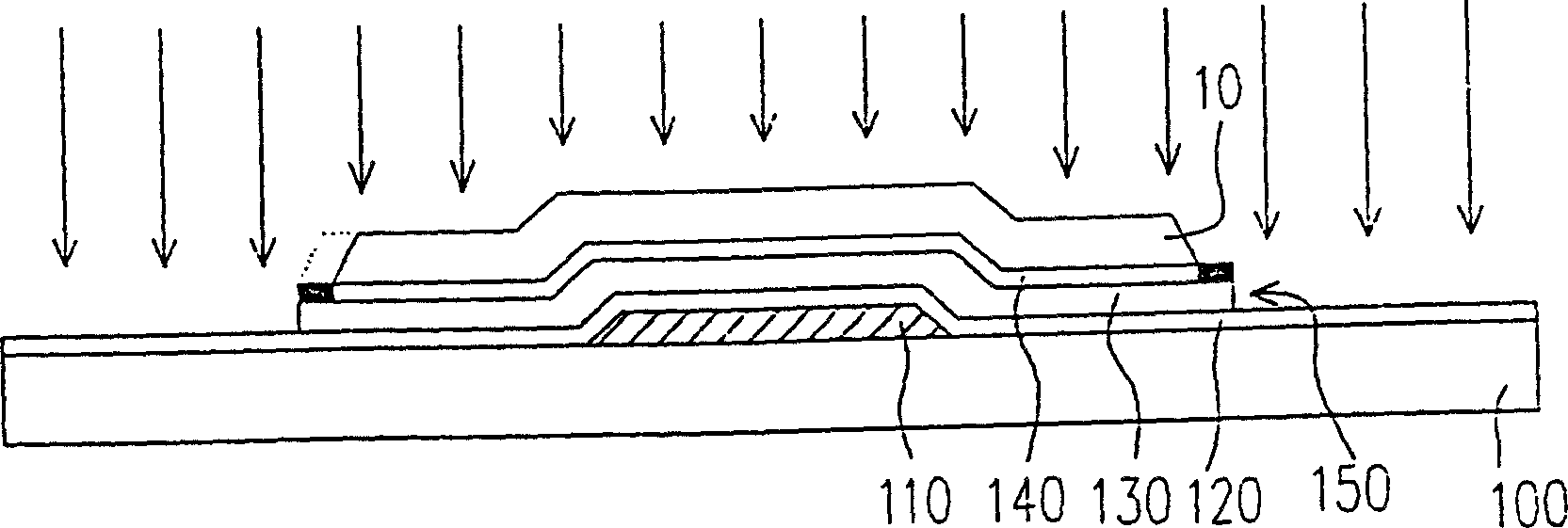
However, when performing dry etching on the ohmic contact layer 140, since the material of the ohmic contact layer 140 located around the channel 150 is silicon dioxide, and the material of other parts of the ohmic contact layer 140 is n+ doped amorphous silicon, therefore The ohmic contact layer 140 located around the channel 150 will remain because the etching rate is slower than that of n+ doped amorphous silicon
[0009] In this way, in Figure 1E The region not shown crosses the source / drain 160 around the channel 150, and will be conducted with each other due to the remaining ohmic contact layer 140, resulting in abnormal display of the liquid crystal display

Method used


Image

  • Etching method and method for manufacturing thin film transistor employing the same
  • Etching method and method for manufacturing thin film transistor employing the same
  • Etching method and method for manufacturing thin film transistor employing the same

Examples


Embodiment Construction

[0016] Figures 3A-3H It is a flow sectional view of a manufacturing method of a thin film transistor according to an embodiment of the present invention, and Figure 4 for Figures 3A-3H Flowchart of the manufacturing method.

[0017] Please refer to Figure 3A and Figure 4 , as in steps S210-S240, the manufacturing method of the thin film transistor of this embodiment first forms the gate 210 on the substrate 200. Next, an insulating layer 220 is formed on the substrate 200 , and the insulating layer 220 covers the gate 210 . Afterwards, a semiconductor layer 230 is formed on the insulating layer 220 . Then, an ohmic contact layer 240 is formed on the semiconductor layer 230 . Wherein, the material of the ohmic contact layer 240 is n+ doped amorphous silicon. In addition, the material of the gate 210 is, for example, chromium, molybdenum or other conductive materials, and the material of the insulating layer 220 is, for example, silicon nitride (SiN x ), the materia...


PUM


Abstract

This invention relates to one film transistor process method, which comprises the following steps: First forming grating electrode on baseboard; Then forming isolation layer on the baseboard covered with grating electrode; Then forming semiconductor layer on the isolation layer; Then forming ohm contact layer on the semi-conductor layer with material of n+ mixture crystal silicon; Then forming channel by semi-conductor layer and ohm contact layer above electrode; Then forming source electrode or leakage electrode on the both sides of channel; Then converting ohm contact layer uncovered source or leakage electrodes surface layer into earth silicon; Then removing ohm contact layer part.

Description

technical field [0001] The present invention relates to a manufacturing method of a semiconductor element, and in particular relates to an etching method and a manufacturing method of a thin film transistor using the etching method. Background technique [0002] The rapid progress of the multimedia society is mostly due to the rapid progress of semiconductor components or man-machine display devices. As far as the display is concerned, the cathode ray tube (Cathode Ray Tube, CRT) has been monopolizing the display market in recent years because of its excellent display quality and economical efficiency. However, for the environment where individuals operate multiple terminals / display devices on the table, or from the perspective of environmental protection, if the trend of energy saving is predicted, there are still many problems in the space utilization and energy consumption of cathode ray tubes. However, there is no effective solution to the requirements of lightness, thi...

Claims


Application Information

Patent Timeline
IPC IPC(8): H01L21/336H01L21/306H01L21/3065
Inventor 郑勉仁许嘉哲张瑞宗
Owner CHUNGHWA PICTURE TUBES LTD
Features
  • Generate Ideas
  • Intellectual Property
  • Life Sciences
  • Materials
  • Tech Scout
  • Unparalleled Data Quality
  • Higher Quality Content
  • 60% Fewer Hallucinations
Learn More