Waveform shaping method, waveform shaping device, electronic device, waveform shaping program, and recording medium

A waveform shaping and pulse width technology, which is applied in the fields of waveform shaping, wave shaping devices, electronic machines, wave shaping programs and recording media, can solve problems such as wireless video transmission system misoperation, failure to work, and inability to restore signals, etc., to achieve simple Effects of reproducibility and simplified configuration

Inactive Publication Date: 2006-05-10
SHARP KK
View PDF1 Cites 8 Cited by
  • Summary
  • Abstract
  • Description
  • Claims
  • Application Information

AI Technical Summary

Problems solved by technology

This is because, along with the photoelectric conversion of the infrared light receiving unit 301, the pulse waveform of the output signal 402 of the infrared light receiving unit is deformed, so the original signal cannot be restored

Method used


Image

  • Waveform shaping method, waveform shaping device, electronic device, waveform shaping program, and recording medium
  • Waveform shaping method, waveform shaping device, electronic device, waveform shaping program, and recording medium
  • Waveform shaping method, waveform shaping device, electronic device, waveform shaping program, and recording medium

Examples


no. 1 Embodiment approach

[0090] The correlative waveform shaping method and the waveform shaping device of the present invention have improved Figure 23 The sampling part 302 of the TV set 207 in the background technology shown in the background art allows the sampling part 302 to correct the deformation of the signal waveform previously generated in the infrared light receiving part 301. In addition, by making it independent of the infrared light receiving part The all-compatible type with the characteristics of 301 can realize a structure in which a digital signal called a remote control signal for wirelessly transmitting information can be accurately reproduced on the wireless station side.

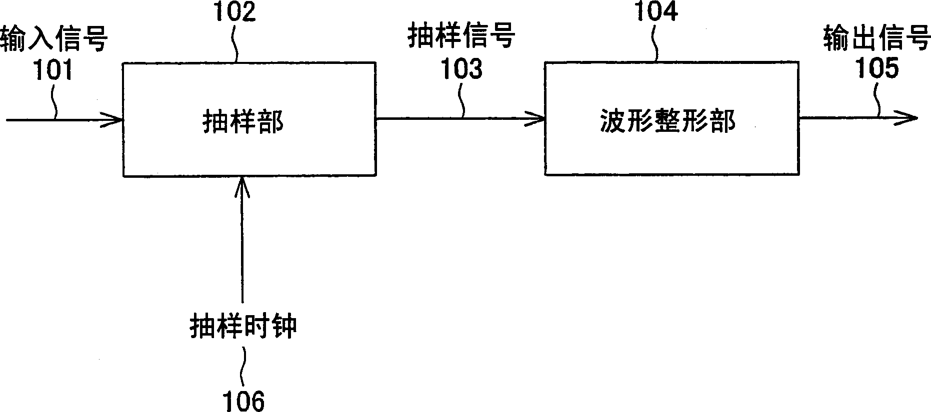
[0091] In the present invention, instead of the above sampling unit 302, such as figure 1 As shown, the improved sampling unit (sampling mechanism) 102 and the waveform shaping unit (waveform shaping mechanism) 104 as the correlation waveform shaping device of the present invention are adopted, and the follo...

no. 2 Embodiment approach

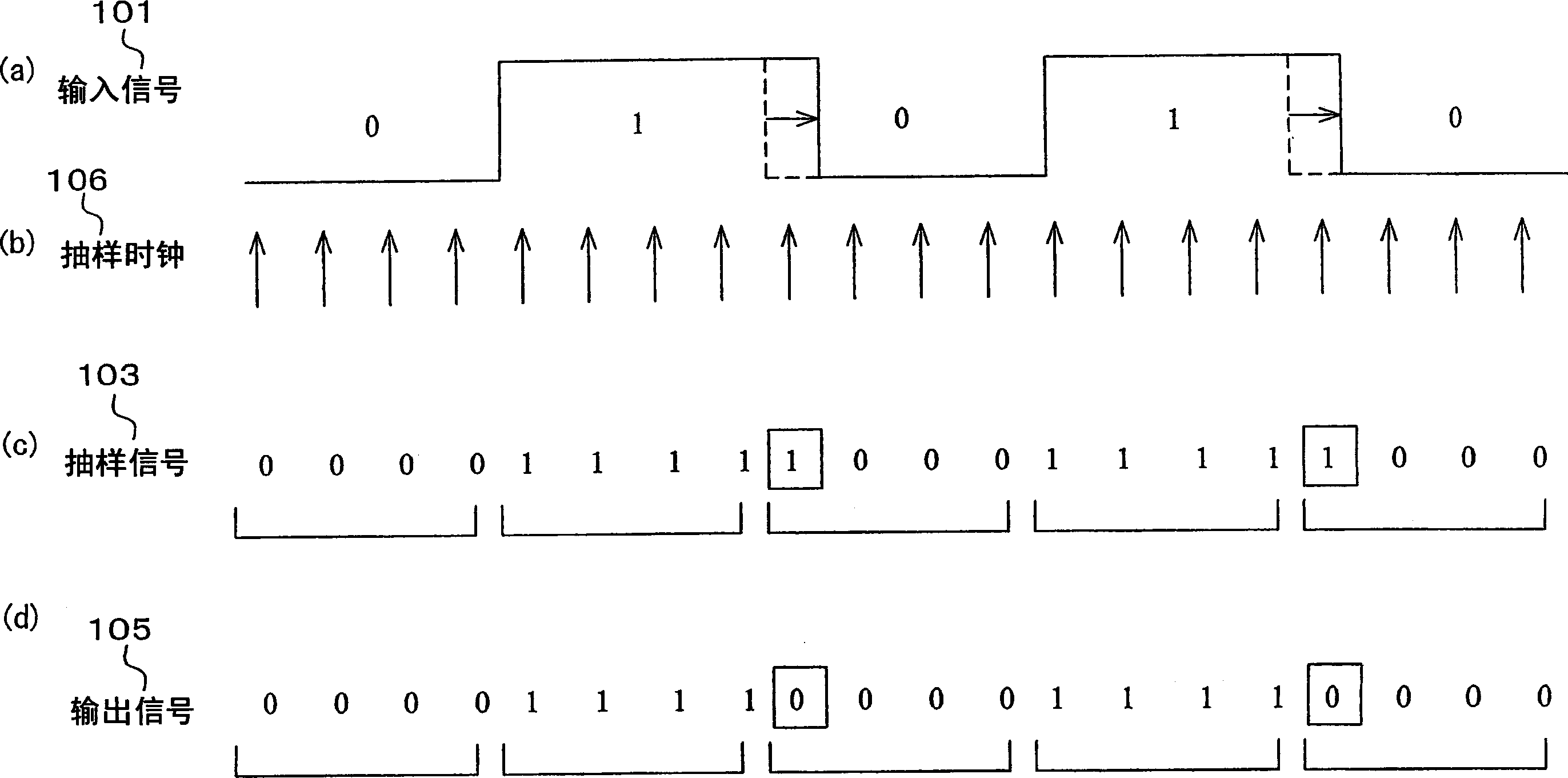
[0143] However, the signal output from the infrared light receiving unit 301 (the input signal 101 input to the sampling unit 102 ) generally tends to be correctly output at the beginning of the pulse, but tends to extend at the rear side of the pulse. In the case of waveform shaping, it can be performed on the rising edge and the falling edge, but considering the above characteristics, if figure 2 (a)~ figure 2 As shown in (d), by performing waveform shaping on the falling edge instead of on the rising edge, not only can the generation of jitter be suppressed, but also the original waveform can be approximated.

no. 3 Embodiment approach

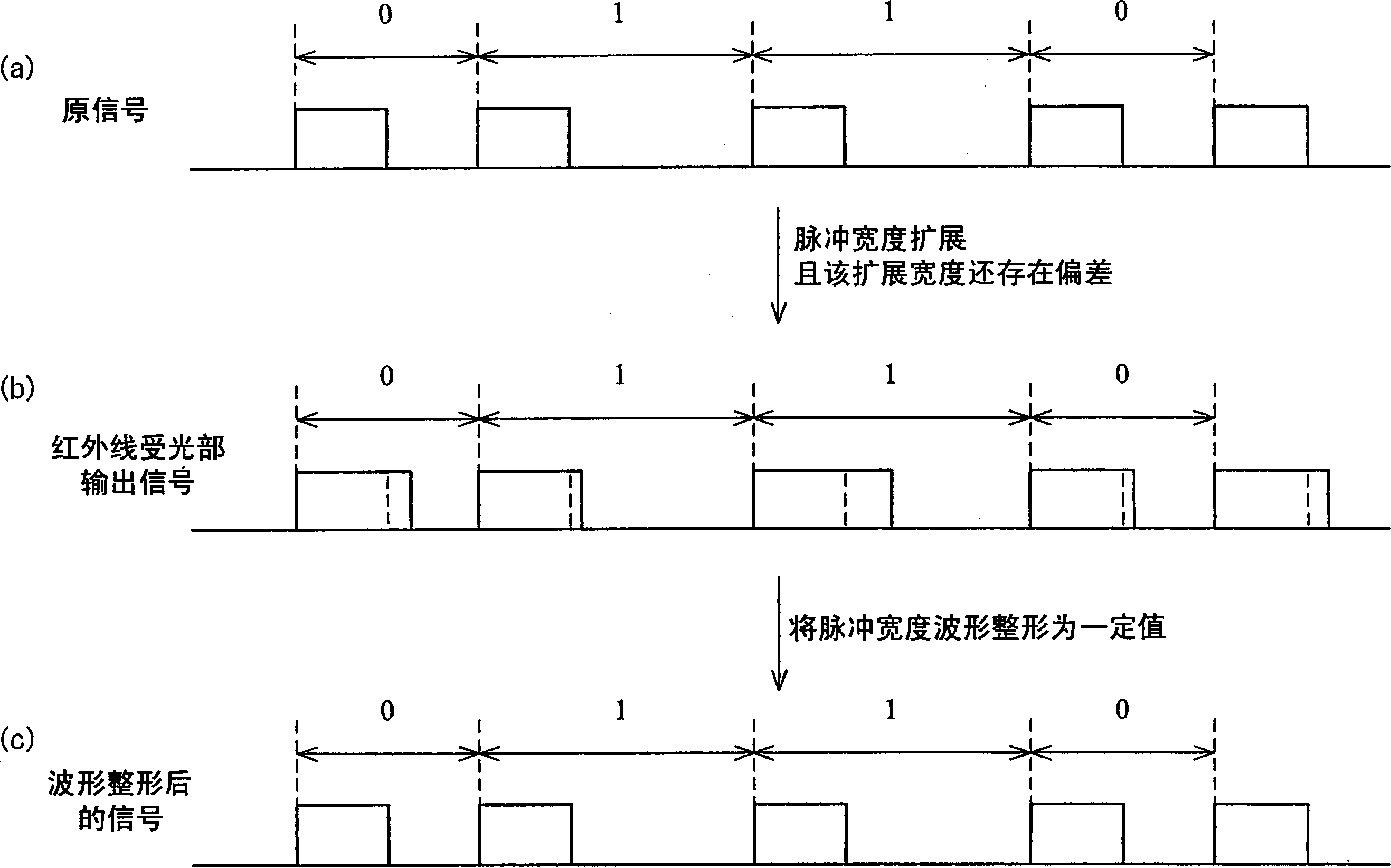
[0145] In general remote control signals, such as image 3 As shown in (a), the pulse width is fixed and the pulse interval is variable. For example, information is transmitted by setting the first interval as data "0" and setting the second interval longer than the first interval as data "1". When the remote control signal is output from the infrared light receiving unit 301, as image 3 As shown in (b), the pulse width is extended, and there is variation in the extended width.

[0146] In this case, as image 3 As shown in (c), regardless of which pulse has distortion, by performing waveform shaping so that all the pulses have a predetermined pulse width, the pulse waveform of the original input signal can be approximated.

[0147] However, when performing communication, the pulse width is usually predetermined. For example, in the remote control code of company A, the pulse width is 250 μs (microseconds), and the data “0” is represented by a pulse interval of 1 ms (mill...


PUM


Abstract

A sampling unit (102) is provided for sampling the input signal (101) by a sampling clock (106) faster than the data rate of the input signal (101) to generate a sampling signal (103). A waveform shaping unit (104) is provided which processes a sampling signal (103) (for example, an inverted pulse) and outputs an output signal (105) obtained by shaping a restored digital signal from the pulse of the input signal (101). In this way, it is possible to provide a waveform shaping method, a waveform shaping device, a waveform shaping program for them, and a storage medium having the program capable of shaping distortion generated in an input signal with a simple method or structure.

Description

technical field [0001] The present invention relates to a method for correctly restoring the original digital signal for reproduction, or for obtaining the same processing based on the original signal even if the pulse waveform of the original signal constituted by the pulse train is deformed. A waveform shaping method, a waveform shaping device, an electronic device, a waveform shaping program for enabling a computer to have the above-mentioned functions, and a storage medium storing the above-mentioned waveform shaping program, which have the same results and are suitable for processing results. Background technique [0002] A remote control (remote control device) is generally used to remotely control machines such as televisions and video recorders. In addition, various companies have also developed wireless TV products (various wireless TVs of the 20LF10 and 14LF10 models produced by Toshiba Co., Ltd., or XF800 and XF-600 models produced by Casio Computer Co., Ltd. A w...

Claims


Application Information

Patent Timeline
IPC IPC(8): H03K5/04H04Q9/00
Inventor 池田丰荒卷隆志
Owner SHARP KK
Why Eureka
Try Eureka