
Automatic navigation lock and water way channel

A ship lock and automatic technology, applied in ship locks, ship lifting devices, water conservancy projects, etc., can solve the problems of slow passing speed, unusable, low ferry efficiency, etc. The effect of a large volume of transport

Inactive Publication Date: 2006-05-31
杨祁东
View PDF1 Cites 18 Cited by
  • Summary
  • Abstract
  • Description
  • Claims
  • Application Information

AI Technical Summary

Problems solved by technology

In addition, the switch and the flushing are two sets of equipment, so the power control equipment used is also very large and complicated, and a large amount of water is required to open the gate every time, because every time a ship passes by, the gate must be opened to enlarge the water, because the ship lock of the gate The chamber is fixed, the water capacity is large, and the water is released once when it is opened, so the water will inevitably be wasted seriously.
In addition, the speed of passing the ship is too slow, because it takes time to release water, store water, wait for the ship and arrange the ship, etc.
Also, because the high water level has strong water pressure on the walls around the lock chamber, the construction project cannot last for a long time, and it needs to be repaired at a high cost.
The unavoidable low ferry efficiency of lift locks and expensive ferry locks require a lot of manpower and material resources to maintain and operate the lock system
[0003] Although the above-mentioned problems can be solved in the published text of the 98104521.9 patent application, what it uses is not a double-layer back-dragon trapezoidal ship lock, and the water rushing down from the gate and directly rushing to the bottom plate cannot meet the trapezoidal work requirements
In addition, the water pressure sensor used is similar to a jack. If the water pressure is high, it will not be able to withstand it. Even if it withstands it, it will not be able to pull it. High precision requirements for over gate closing
Moreover, it is very dangerous for a ship to sail in a passive lock, so it cannot be used

Method used


Image

  • Automatic navigation lock and water way channel
  • Automatic navigation lock and water way channel
  • Automatic navigation lock and water way channel

Examples


Embodiment Construction

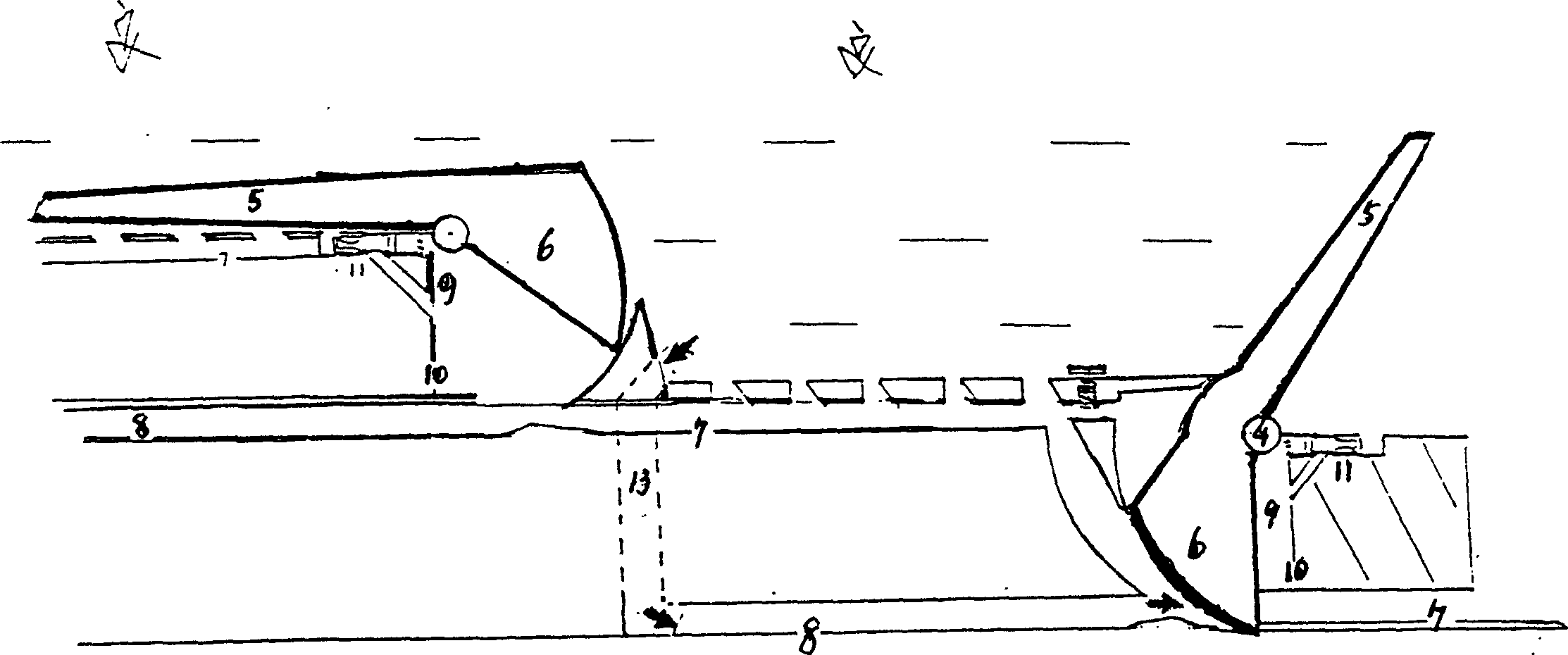
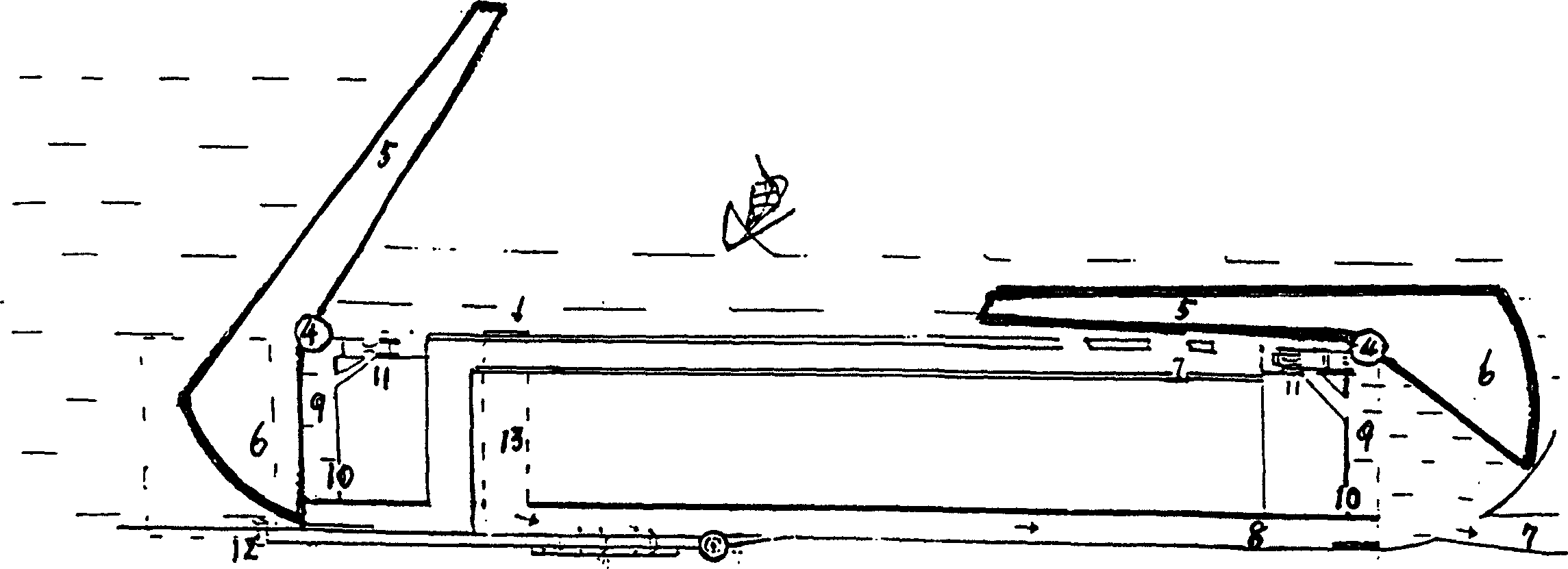
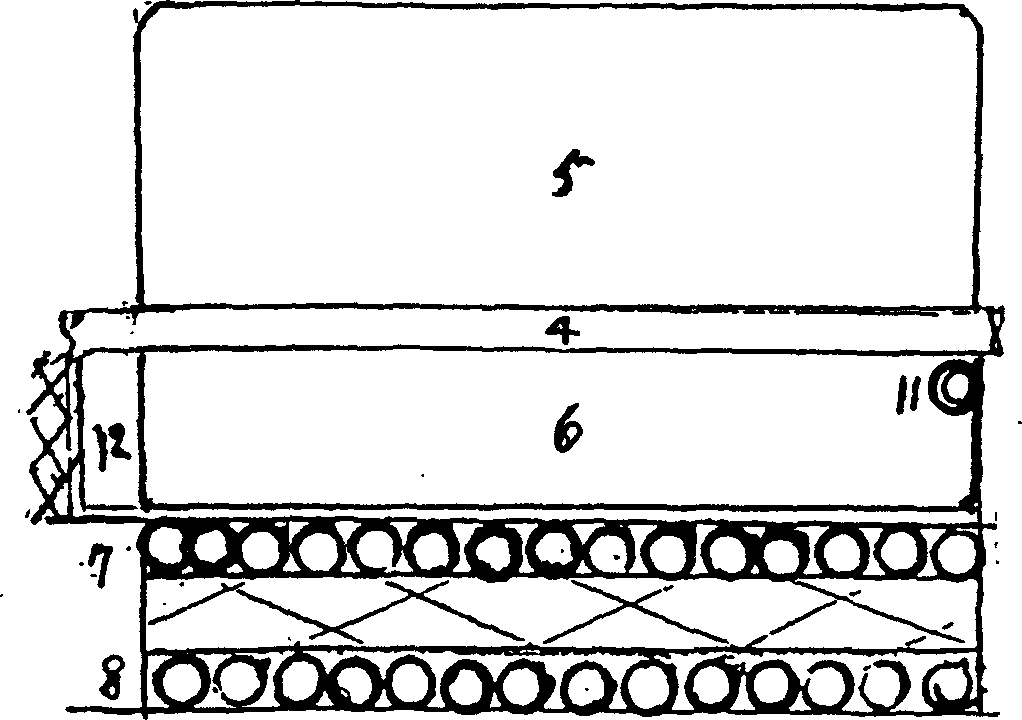
[0028] Such as Figure 4 As shown, the ship lock has a water grab 1 in the water channel at the back gate of the ship lock chamber, and at the same time, there is a covert channel 2 on the bottom plate. The ship has passed the first gate, and now the position of the middle lock chamber is preparing to enter the second gate. room, such as figure 2 It is a schematic diagram of the position of some ship locks when the ship is running in the channel. As shown in the figure, the upper gate 5 and the lower gate 6 are integrated and installed on the horizontal shaft 4. The lower gate 6 and the floor lip wall 10 are combined to form a hydraulic reaction chamber. 9. The water pressure reaction chamber 9 is connected to the infrared induction water pressure tee piston 11. There is a lower flushing and discharging channel 8 of the upper lock chamber under the hydraulic reaction chamber 9, and the lower flushing and discharging channel 8 is horizontally connected to the upper flushing and ...


PUM


Abstract

This invention is an automatic ship lock. The lower lock gate and the lip wall of the lock chamber floor forms a water pressure reflecting room. To the room installed an infra sensor tee piston. To the bottom of the room is the end drop channel of the main lock, followed by down sluicing channel and the lower lock gate, then the horizontal up sluice channel. To the end of the room is the drop channel followed by a vertical channel then to the horizontal down sluice channel to form a two layer recycle sluice. The upper and the bottom gates form a single or multi lock chamber. In the water pressure reflecting room, there is a power switch and an infra sensor switch to control the tee piston and water level separately. With the use of water pressure balance theory to eliminate the huge water head pressure and the shipí»s drive power makes it possible for the ship to pass the ship lock at the same speed. The ship lock is capable of automatically control water make-up, leakage and flood protection.

Description

Technical field: [0001] The present invention relates to a ship lock, in particular to a ship lock project that can automatically and quickly open, close, flush, and discharge water levels through water pressure induction (it does not involve any internal structural problems in the current various ship lock systems including the Three Gorges five-level ship lock and the lifting ship lock, etc. It is a new independent system of ship lock project) waterway channel aimed at improving the transportation of bare waste rivers and new development and use. Background technique: [0002] The current ship lock system is very complicated and heavy, so when the water level of the dam is high, the number of ship lock stages should be reduced as much as possible, or the ship lock should be changed to a one-time elevator ship lock. Its disadvantage is that because the water pressure of the tens of meters high dam rushes to the wall, it is necessary to build a large construction project in ...

Claims


Application Information

Patent Timeline
IPC IPC(8): E02C1/06E02B7/42
CPCY02A10/30
Inventor 杨孔明杨祁东
Owner 杨祁东
Learn More