Method for Making scintillator layer for x-ray detector, scintillator layer

A scintillator and detector technology, which is applied in chemical instruments and methods, X-ray/infrared technology, radiation intensity measurement, etc. Effect

Inactive Publication Date: 2006-05-31
SIEMENS AG
View PDF0 Cites 19 Cited by
  • Summary
  • Abstract
  • Description
  • Claims
  • Application Information

AI Technical Summary

Problems solved by technology

But this in turn leads to the following drawback: the X-ray beam falling on the scintillator layer is not completely absorbed and thus deteriorates the quantum efficiency of such planar image detectors
Finally, a scintillator layer made of CsI:T1 also has the disadvantage that this scintillator layer is hygroscopic and must therefore be effectively protected from air humidity

Method used


Image

  • Method for Making scintillator layer for x-ray detector, scintillator layer
  • Method for Making scintillator layer for x-ray detector, scintillator layer
  • Method for Making scintillator layer for x-ray detector, scintillator layer

Examples


Embodiment Construction

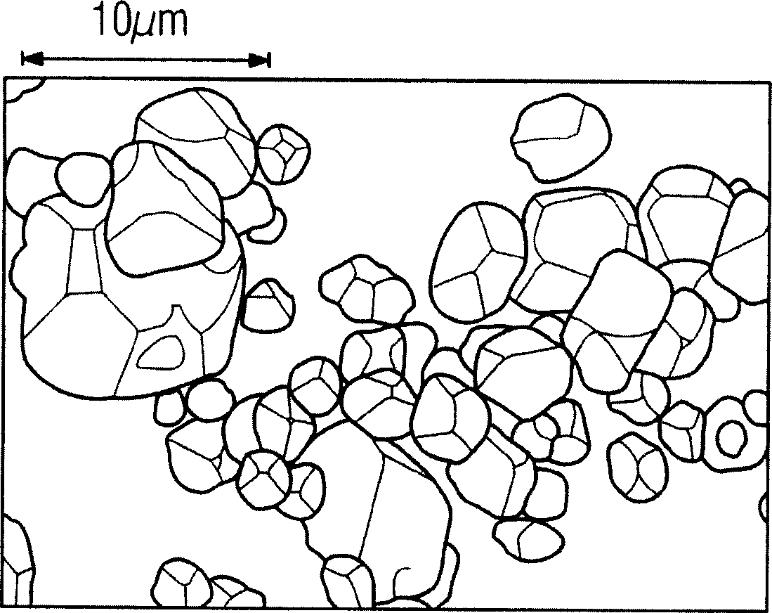
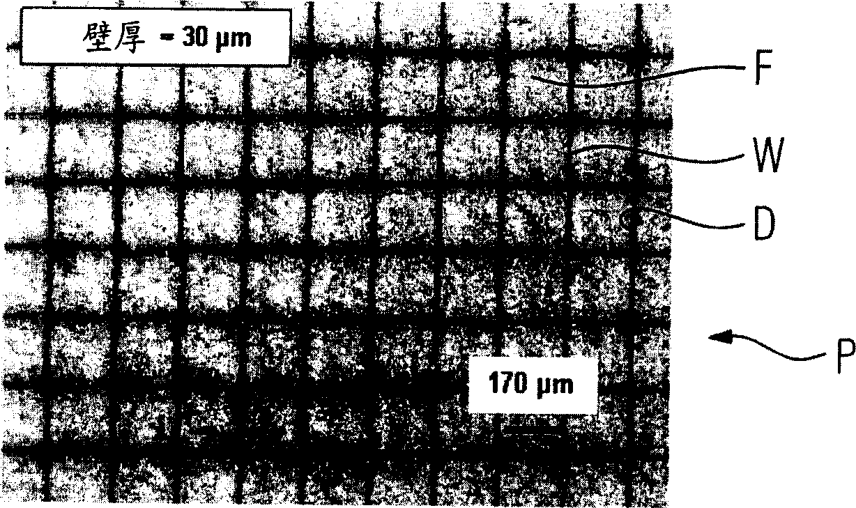
[0028] for manufacturing figure 2 The first scintillator layer shown uses a plastic plate P made of epoxy resin. The plastic plate P has a thickness of 2 mm and external dimensions of 20×20 mm. Punch D is basically square. Its open area has an edge length of approximately 170×170 μm. The perforations D are separated from each other by a wall W, the wall thickness of which is about 30 μm. The production of such a plastic sheet P takes place in a conventional manner, for example by means of stereolithography. For the manufacture of filler F for example using figure 1 Gd shown 2 o 2 S phosphor. Such as figure 1 As shown, the Gd 2 o 2 The maximum particle diameter of the S phosphor is about 10 μm. (Merck) Paraffin wax is liquid at 80 to 100°C, and Gd with an average particle size of about 21nm is added 2 o 2 S phosphor. Here, the quantity ratio in filler F is set such that Gd 2 o 2 The S phosphor accounts for about 70% by mass, and the paraffin wax accounts for ab...


PUM


Abstract

The invention relates to a scintillator layer for a position-resolved X-ray detector, in which the perforations (D) arranged in a plate (P) and formed in the form of a grating are filled with polymers and phosphors (F) Filling.

Description

technical field [0001] The invention relates to a method for producing a scintillator layer for an X-ray detector and to a scintillator layer. Background technique [0002] From the prior art, so-called planar image detectors are known for detecting X-ray beams. Such planar image detectors were first used in digital radiography. Planar image detectors include, for example, CsI:T1 or Gd 2 o 2 S: A scintillator layer made of Tb, which is laid on a photodiode array formed of photodiodes. In order to achieve the best possible image resolution, the scintillation light needs to be collected only by those photodiodes that are just vertically below where the scintillation light occurs. In practice, however, depending on the microstructure of the scintillator layer, the scintillation light emitted from the point of emergence is more or less strung to adjacent photodiodes. In order to improve the positional resolution of such planar image detectors, attempts have been made to min...

Claims


Application Information

Patent Timeline
Patent Type & Authority Applications(China)
IPC IPC(8): G21K4/00G01T1/20
CPCC09K11/7701G21K4/00G21K2004/06G21K2004/08B33Y80/00
Inventor 凯恩·费姆贾沃尔夫冈·罗斯纳
Owner SIEMENS AG
Why Eureka
Try Eureka