Multistage gas solie chemical reactor

A chemical reactor, gas-solid reactor technology, applied in chemical instruments and methods, chemical/physical processes, etc., can solve the problems of large reaction gas flow resistance, high cycle power consumption, unreasonable structure of gas-solid chemical reactor, etc. , to achieve the effect of small cycle power consumption, small heat exchange area and simple structure

Active Publication Date: 2006-06-14
HUNAN ANCHUN ADVANCED TECH
View PDF0 Cites 6 Cited by
  • Summary
  • Abstract
  • Description
  • Claims
  • Application Information

AI Technical Summary

Problems solved by technology

[0002] The structure of the existing gas-solidification chemical reactor used in the synthesis of ammonia or methanol is not reasonable. Due to the low temperature out of the tower, it can only produce 1.2-2.5Mpa saturated steam, and the resistance of the reaction gas flow is relatively large, and the cycle consumes more power. ,Room for improvement

Method used


Image

  • Multistage gas solie chemical reactor
  • Multistage gas solie chemical reactor

Examples


Embodiment Construction

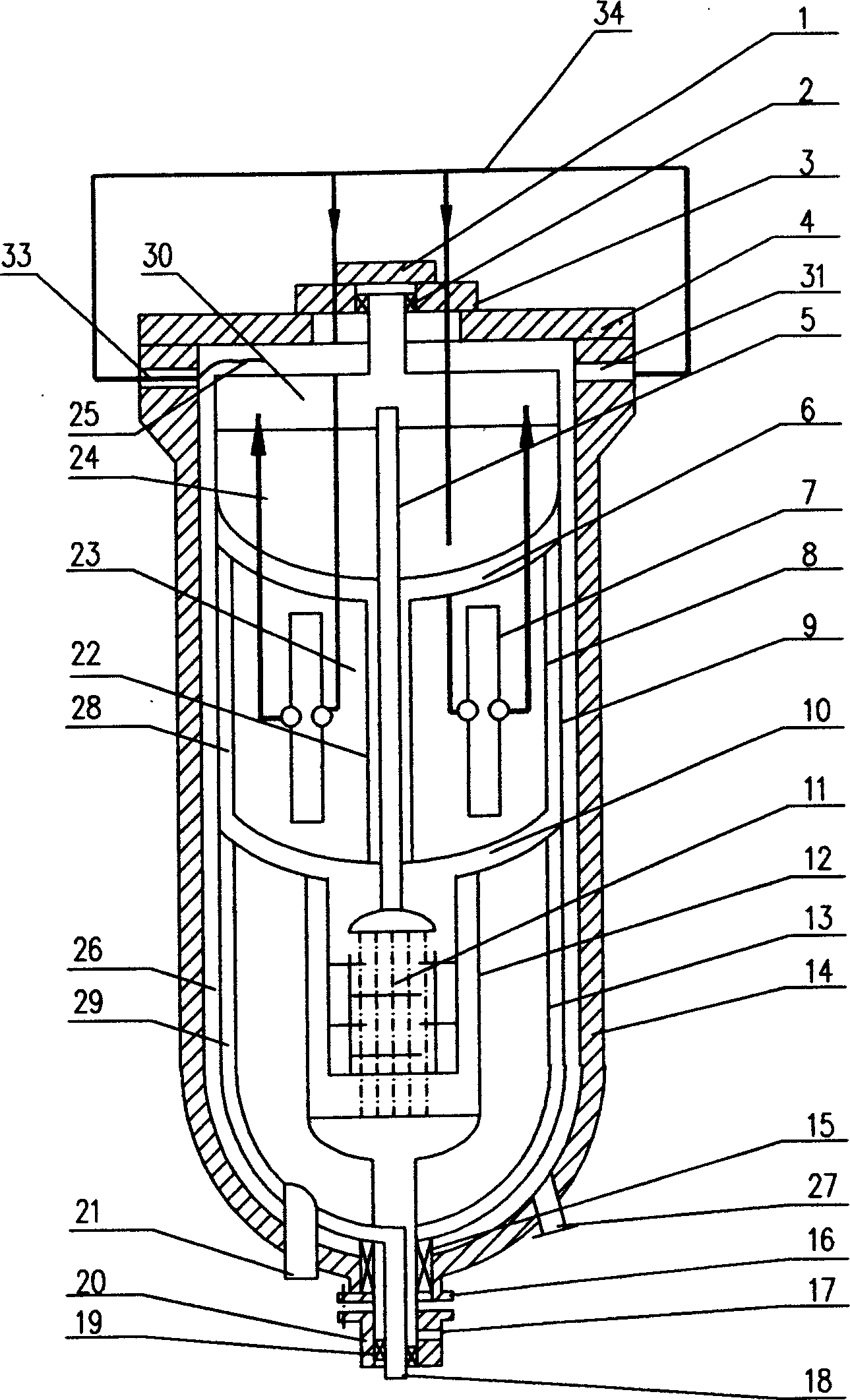
[0037] According to the present invention device of accompanying drawing and above-mentioned structure, the top cover of pressure outer cylinder 14 tops is as figure 1 The device shown is composed of a large cover 4, a middle cover 3, and a small cover 1 stacked in sequence from bottom to top. The large cover 4 is opened only rarely when the inner cylinder is assembled for the first time (including large, medium and small) , in the future only open the middle and small caps, load the catalyst or check and maintain the internal parts.

[0038] There is a tee at the bottom of the reactor, which is composed of two pressurized hollow joints. The upper joint 16 is welded to the bottom of the pressure outer cylinder 14. The lower joint 20 is connected to the upper joint by a flange. The lower part can be flanged or directly Welded connections to pipes or steam generators.

[0039] A packing seal 15 is added between the upper sub-section 16 and the inserted unreacted gas inlet pipe,...


PUM


Abstract

A multi-segment chemical gas-solid reactor is composed of a pressurized external cylinder and a heated internal cylinder, which has three layers, two pot-shaped gas collectors between adjacent two layers, and two heat exchangers installed respectively in the centers of the second and the third layers. Its advantages are high purity of product, high grade of vapor and low airflow resistance.

Description

technical field [0001] The invention relates to a multi-stage gas-solidification chemical reactor for synthesis of ammonia or methanol. Background technique [0002] The structure of the existing gas-solidification chemical reactor used in the synthesis of ammonia or methanol is not reasonable. Due to the low temperature out of the tower, it can only produce 1.2-2.5Mpa saturated steam, and the resistance of the reaction gas flow is relatively large, and the cycle consumes more power. ,Room for improvement. Contents of the invention [0003] The technical problem to be solved by the present invention is to propose a multi-stage gas-curing chemical reactor in view of the defects in the prior art, which has a simple structure, high net value of ammonia produced, and can produce superheated steam with higher temperature and pressure while utilizing energy High efficiency, low cycle power consumption, remarkable energy-saving effect. [0004] The technical solution of the pre...

Claims


Application Information

Patent Timeline
Patent Type & Authority Applications(China)
IPC IPC(8): B01J8/04
Inventor 谢定中李彬
Owner HUNAN ANCHUN ADVANCED TECH
Why Eureka
Try Eureka