Projection system with total reflection prism

A technology of total reflection prism and projection system, applied in prisms, optics, instruments, etc., can solve the problems of thin projection products, low light efficiency of the optical system, and increased volume of the optical system, and achieve simple structure and small size The effect of improving the volume and optical efficiency

Inactive Publication Date: 2006-06-21
深圳市欧曼特微显示科技有限公司
View PDF0 Cites 13 Cited by
  • Summary
  • Abstract
  • Description
  • Claims
  • Application Information

AI Technical Summary

Problems solved by technology

However, using the above-mentioned optical path structure of the traditional TIR prism structure, a folding reflector is required in the optical path to guide the light beam from the light source to the total reflection TIR prism, which will lose about 2% of the reflected light
[0006] Moreover, due to the large-angle reflector, after the reflector, it is necessary to add a lens to shape the illumination spot to meet the requirements of the DMD for the spot, but this will cause the loss of the illumination beam by about 2%.
[0007] Moreover, since the DMD is fixed on the lower surface of the TIR

Method used


Image

  • Projection system with total reflection prism
  • Projection system with total reflection prism
  • Projection system with total reflection prism

Examples


Embodiment Construction

[0042] The implementation of the present invention will be described in detail below in conjunction with the accompanying drawings.

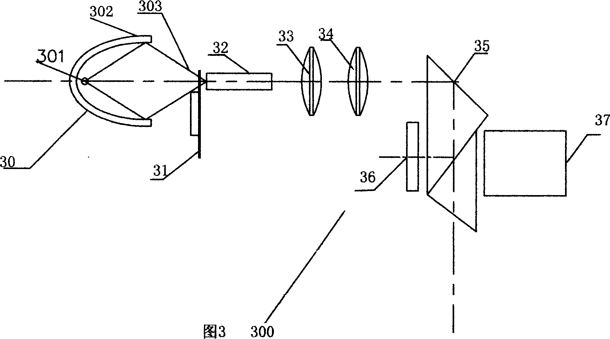
[0043] Please refer to FIG. 3 , the projection system 300 of the projection display device according to the first embodiment of the present invention mainly places a prism 351 (a first prism, also a prism one) between a light source 301, a microdisplay device 36 and a projection lens 37 352 (the second prism is also prism two), the cemented prism group TIR prism 35 that prism 351 and 352 form, wherein the light source is located at the side of the prism away from the total reflection surface, and the micro-display device 36 and the projection lens 37 are respectively arranged on the prism The two sides of , that is, the first surface 3501 and the exit surface 3505 (combined Figure 4 ), forming a projection system.

[0044] The light source system 30 of the projection system 300 of this embodiment is composed of a wick 301 and a reflective lamp...


PUM


Abstract

The invention discloses a projection system with total reflection prism, which consists of light source and TIR prism structure, wherein the TIR prism structure reflects the injection light beam into the DMD part and projection lens, which realizes the projection display; the system can project the image on the display screen through rotating the microlens reflective light.

Description

technical field [0001] The invention relates to an optical device of a TV display screen, specifically a total internal reflection prism optical prism system used for a digital microreflection mirror device and a projection display system using the prism system. Background technique [0002] With the development of computer and information display technology, many new display technologies have emerged, such as DLP, LCOS, CRT, LED, etc. Not only that, as a projection display device, can its picture quality performance have high resolution and high contrast? Brand-new products with features such as high brightness, low price, etc., which are accepted by the consumer market, have become an important subject of research and development in this field. [0003] Usually, micro-mirror structure devices are used in DLP reflective projection systems. This micro-mirror structure display device is composed of many tiny mirrors. Each micro-mirror is independently controlled by CMOS, and ...

Claims


Application Information

Patent Timeline
IPC IPC(8): G02B27/18G02B5/04
Inventor 王芳芹詹达举杨福中
Owner 深圳市欧曼特微显示科技有限公司
Why Eureka
Try Eureka