
Optical switch

An optical switch and side light technology, applied in the field of optical switches, can solve the problems of poor adjustment, reduced optical switch productivity, low efficiency, etc., and achieve the effects of reducing insertion loss, reducing driving parts, and seeking miniaturization

Inactive Publication Date: 2006-06-21
ORMON CORP
View PDF0 Cites 0 Cited by
  • Summary
  • Abstract
  • Description
  • Claims
  • Application Information

AI Technical Summary

Problems solved by technology

[0005] But because this kind of optical switch needs to have the optical path switch mechanism that is made of the first and second reflection mirrors and driver, so just need to have the bigger space that is used for disposing switch mechanism between input-side optical fiber and output-side optical fiber, from The optical path length of the light emitted from the optical fiber on the input side of the optical switch and injected into the optical fiber on the output side increases, and the insertion loss of the optical signal in the optical switch increases.
Or if you want to supplement the insertion loss to achieve low loss in the optical switch, you must perform optical axis alignment of the input side and the output side optical fiber with high precision, which may reduce the productivity of the optical switch.
[0006] In order to reduce the space between the optical fiber on the input side and the optical fiber on the output side, it is necessary to reduce the size of the switch mechanism, so technologies such as micro-machining technology MEMS (Micro-Electro-Mechanica Systems) are required, and there is a problem that the price of the optical switch is very high.
Moreover, since multiple reflectors and drivers are required (16 in an 8×8 rectangular optical switch), the efficiency is not high, poor adjustment and failure are prone to occur, and the manufacturing cost is also high.

Method used


Image

  • Optical switch
  • Optical switch
  • Optical switch

Examples


no. 1 example

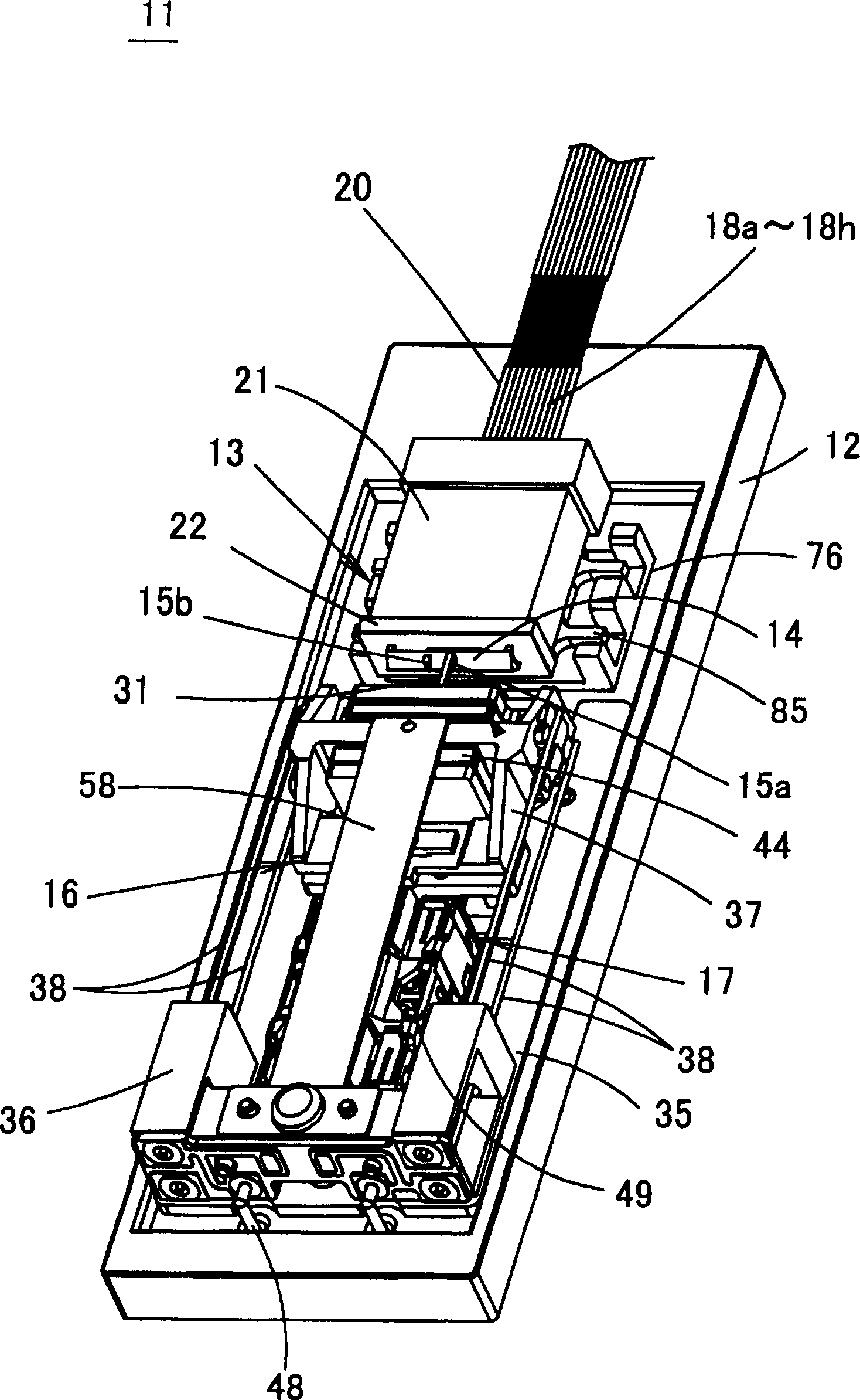
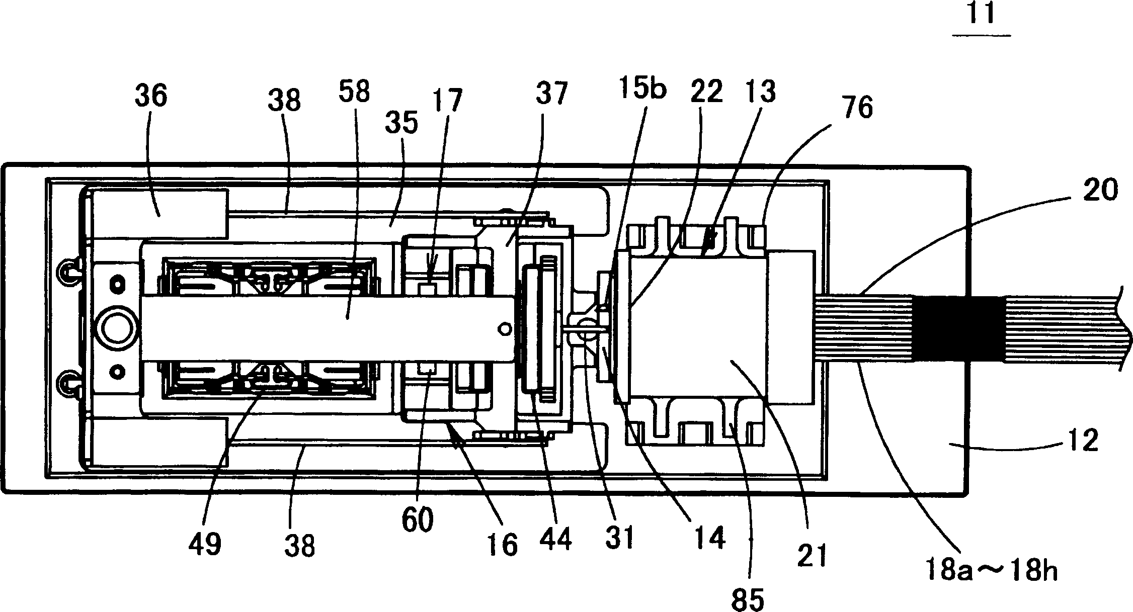
[0045] figure 2 is a perspective view of the optical switch (standby optical switch) of the first embodiment of the present invention, image 3 is its floor plan, Figure 4 is its side view. In this optical switch 11 , an input / output unit 13 , a prism driving unit 16 and a positioning unit 17 are mounted on a base 12 made of ceramics, metal, plastic, or the like. A fixed prism 14 is attached to the input / output section 13, a prism 15b for a preliminary fiber is attached to the fixed prism 14, and a prism driving section 16 holds the driving prism 15a.

[0046] The input / output unit 13 is provided with: a plurality of input-side optical fibers (fiber array) 18a to 18h serving as an input-side optical transmission path, a plurality of output-side optical fibers (fiber array) 19a to 19h to be an output-side optical transmission path, and a single backup optical fiber. (spare optical fiber) 20, and they are bundled into one by connectors 21 such as MT connectors. Figure 5 (...

no. 2 example

[0082] Figure 22 It is a perspective view showing the structure of an optical switch in other embodiments of the present invention, Figure 23 is its floor plan, Figure 24 is its side view. This optical switch 91 has substantially the same structure as that of the optical switch 11 of the first embodiment except for the structure of the positioning portion 17 . That is, in the positioning portion 17 of the optical switch 91 , the base end portion of the leaf spring 92 bent into a step shape is joined to the upper surface of the front end portion of the movable iron piece 63 of the electromagnetic driver 49 . A pressing protrusion 93 for pressing the prism holder 37 is provided on the lower surface of the front end portion of the leaf spring 92 . It directly presses the prism seat 37 through the leaf spring 92 installed on the movable iron piece 63 .

[0083] Next, the operation of this optical switch 91 will be described. Under the situation that the electromagnetic dri...


PUM


Abstract

An optical switch comprising two layers of input-side optical fibers and backup optical fibers arranged side by side and output-side optical fibers arranged side by side, and a fixed prism (14) arranged facing their end faces. On one side slope of the fixed prism (14), a prism (15b) for the preparation fiber is arranged opposite to the preparation fiber (20), so that the drive prism (15a) can be contacted and separated from the side slope of the fixed prism (14). The driving prism (15a) can move along the input side optical fiber. When the driving prism (15a) is in contact with the position on the slope of the fixed prism (14), the outgoing light from the input-side optical fiber is not totally reflected by the slope of the fixed prism (14) and enters into the driving prism (15a), and is transmitted from the driving prism (15a). After the prism (15a) is sent out to the prism (15b) for the preliminary fiber, it enters the preliminary fiber (20) from the prism (15b) for the preliminary fiber. With this optical switch, the insertion loss can be reduced, and the stroke of the driving part can also be shortened.

Description

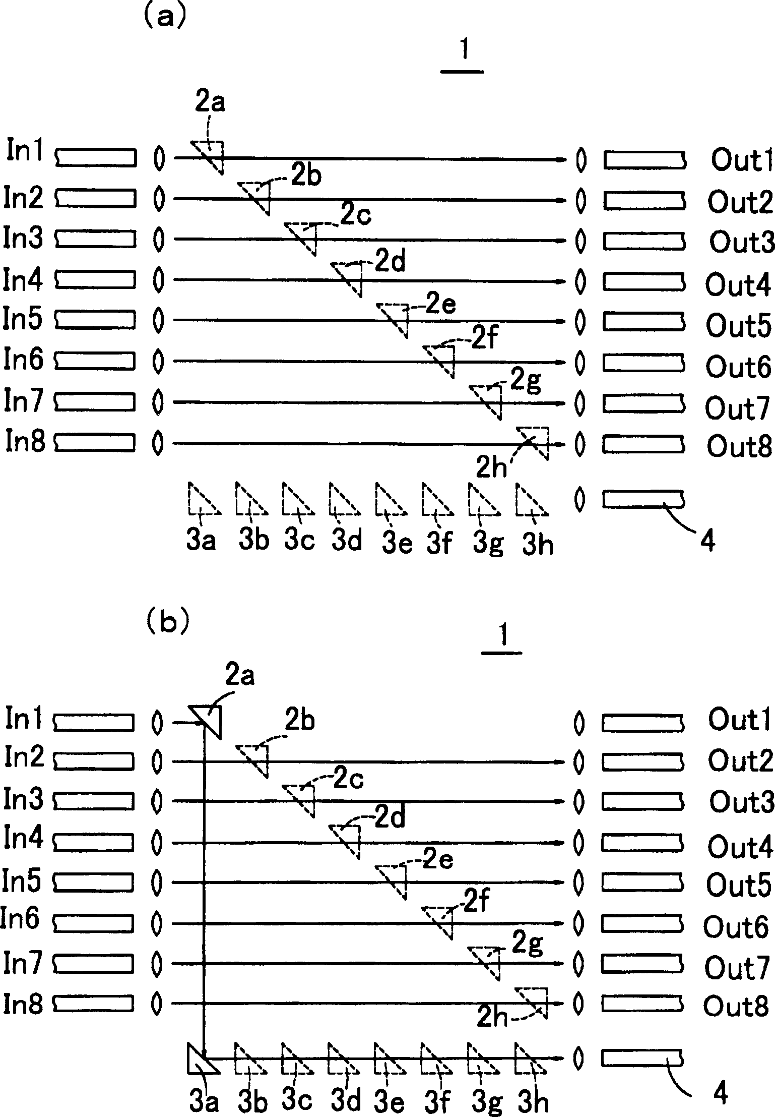
technical field [0001] The invention relates to an optical switch, in particular to an optical switch used as an optical communication device. Background technique [0002] The principle of the existing standby optical switch (8×8 rectangular optical switch) is expressed in figure 1 (a). In this optical switch 1, an input-side optical fiber bundle composed of eight input-side optical fibers In1-In8 is opposed to an output-side optical fiber bundle composed of eight output-side optical fibers Out1-Out8. In the space between Out1 to Out8, a plurality of first reflection mirrors 2a to 2h are arranged in a pair of diagonals facing each of the input side optical fibers In1 to In8 and forming an angle of 45°. Outside the spaces between the input-side optical fibers In1-In8 and the output-side optical fibers Out1-Out8, the second reflectors 3a-3h are respectively arranged in the reflection directions of the light of the first reflectors 2a-2h. In the reflection direction of the ...

Claims


Application Information

Patent Timeline
Patent Type & Authority Applications(China)
IPC IPC(8): G02B26/08G02B6/32G02B6/35
CPCG02B6/32G02B6/352G02B6/3556G02B6/3572G02B6/358G02B6/3582G02B26/0883G02B2006/12145
Inventor 山本竜田中宏和大西正泰仲西阳一川本竜二铃木裕一
Owner ORMON CORP
Learn More