Bed die floating regulating mechanism of powder forming machine

A floating adjustment and forming machine technology, applied in the direction of presses, manufacturing tools, etc., can solve the problems of unsynchronized action of the linkage mechanism, complex structure of the linkage mechanism, poor structural stability, etc., and achieves easy assembly, simple structure, and adjustable speed. quick effect

Active Publication Date: 2006-06-28
严俏敏
View PDF1 Cites 13 Cited by
  • Summary
  • Abstract
  • Description
  • Claims
  • Application Information

AI Technical Summary

Problems solved by technology

However, in this patent, the linkage mechanism under the first and second rods of the two cams has a complex structure, many parts, troublesome processing and a

Method used


Image

  • Bed die floating regulating mechanism of powder forming machine
  • Bed die floating regulating mechanism of powder forming machine
  • Bed die floating regulating mechanism of powder forming machine

Examples


Embodiment Construction

[0014] Embodiments of the present invention will be further described below in conjunction with the accompanying drawings.

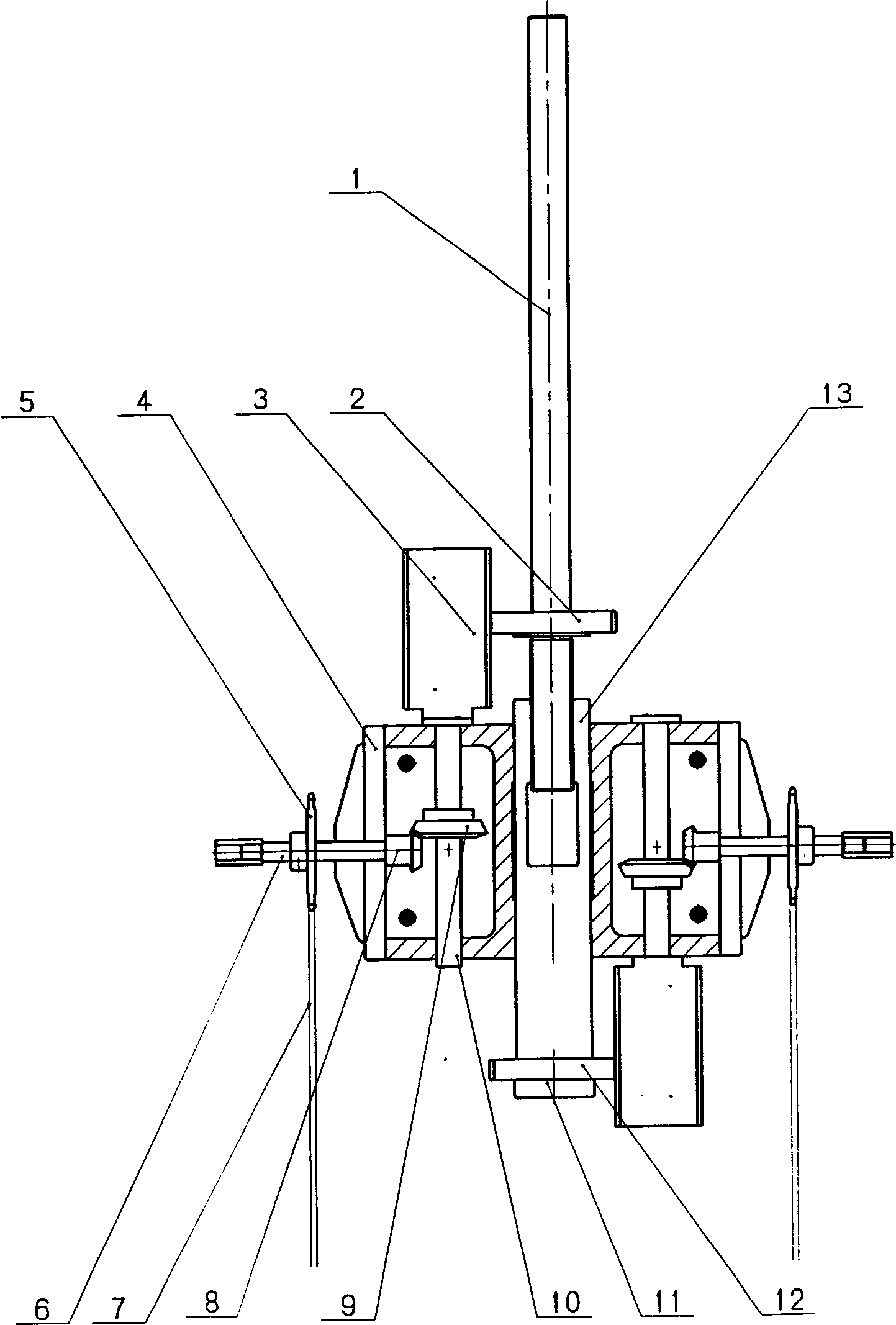
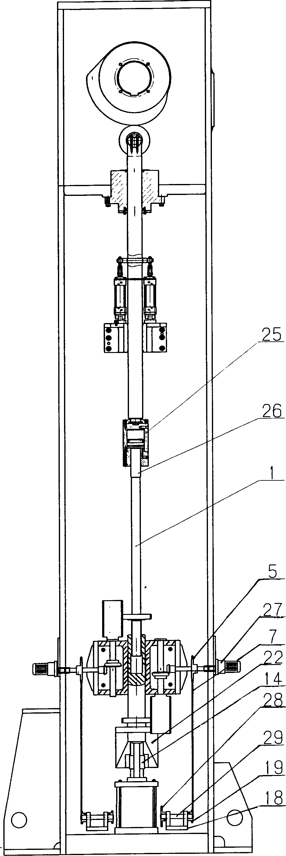
[0015] The hole end of the blind hole in the middle of the adjustment column 13 upper ends has an internal thread, and the end is connected with a driven gear 12, and the lower surface is fixed with a screw pad 11, so that the driven gear 12 can be stopped from moving down, and it can be replaced after long-term work wear.

[0016] The lower end of the adjustment rod 1 is a screw rod, and the outside is connected with a driven gear 2, and the adjustment rod 1 is threaded into an integral lower pressure rod through the lower end screw rod and the blind hole end of the adjustment column 13.

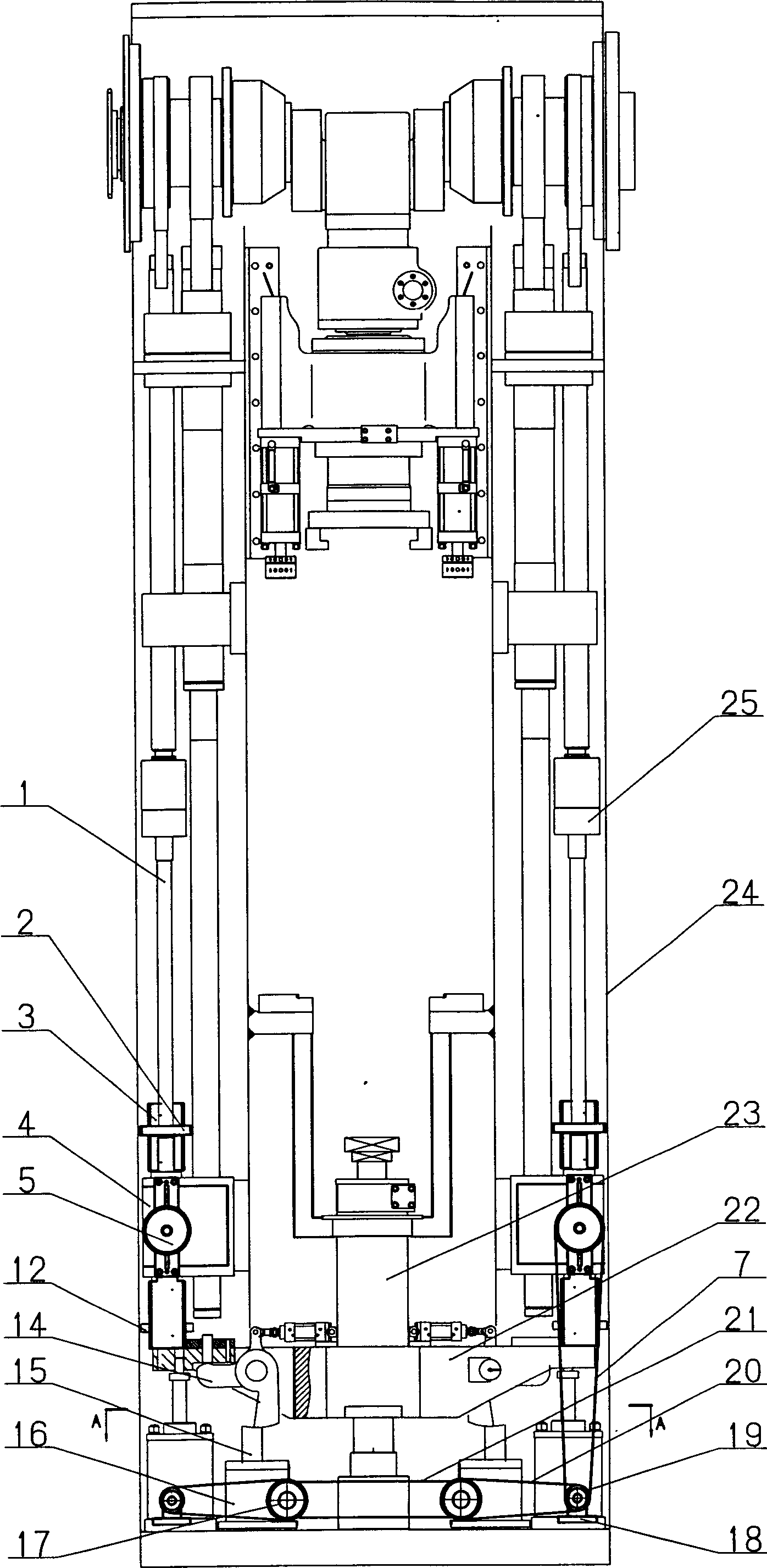
[0017] The two gear racks 4 are respectively symmetrically fixed on the outer surfaces of the two side walls of the frame 24 with screws, and the adjustment column 13 on the lower pressure rod is installed in the middle cavity of the gear rack 4, and the upper and lowe...


PUM


Abstract

A floating regulating mechanism for the female mould of powder shaper is composed of a regulator consisting of the regulating rod with driven gear, lower pressing rod, gear shaft with driven bevel gear and drive gear, the drive shaft with main chain wheel and drive bevel gear and gear holder, a drive unit consisting of drive shaft and power source, two stop block boxes with warm axles having chain wheels, and another drive chain. Its advantages are synchronous regulation and long service life.

Description

technical field [0001] The invention relates to a main component adjustment mechanism in a powder forming machine, which is used for adjusting the downward floating distance of a female mold to ensure uniform density of pressed products. Background technique [0002] Due to its wide application range, high production efficiency and high material utilization rate, the powder forming machine has been widely used in various metal, ceramic, bakelite and other powder products, and the shape of the pressed products is becoming more and more complicated. [0003] Patent No. 00262603.9 "Powder Forming Machine" only mentions the use of chains, sprockets, worm wheels, and worms to control the total length between the spring and the gear. If the length between the spring and the gear is adjusted to make it longer, the gear at the bottom of the spring can be moved earlier. Contact with the connecting mechanism on the lower template to carry out the re-pressing action of the upper punch....

Claims


Application Information

Patent Timeline
IPC IPC(8): B30B15/00
Inventor 严培义
Owner 严俏敏
Why Eureka
Try Eureka