Optical coupler
A technology of optical coupler and input light, which is applied in the field of applied optics and optoelectronics, can solve the problems of not finding the same technical records and reports, and achieve the effect of simplifying the structure, simplifying the optical system, and ensuring concentration and utilization
- Summary
- Abstract
- Description
- Claims
- Application Information
AI Technical Summary
Problems solved by technology
Method used
Image

Examples
Embodiment 1
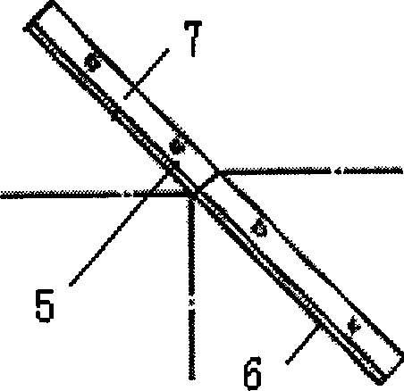
[0037] Embodiment 1: see image 3 , the optical coupler 5 of the present invention, the transparent object is glass 7, and its shape is a flat plate, and one surface on the transparent object is coated with an anisotropic polarization beam splitting dielectric film 6, which is a realization of the optical coupler of the present invention the simplest structure. The transparent body 7 is an optical glass plate, on which any one surface is coated with an anisotropic polarization beam splitting dielectric film 6; Thus, the photocoupler 5 is constituted. Wherein, the normal line of the film surface of the coated anisotropic polarization beam-splitting dielectric film 6 forms an angle of 45 degrees with the optical axis of the input beam. The thickness of the optical glass plate is about 1mm, and the shape and size are determined according to the clear aperture.
[0038] The oxide dielectric film layer is made of silicon oxide dielectric film layer and titanium oxide dielectric ...
Embodiment 2
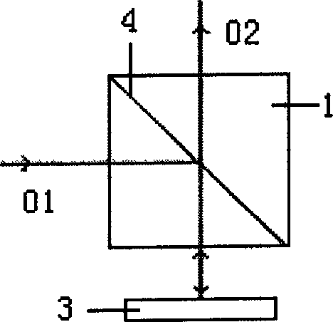
[0040] Such as Figure 4 Shown is a structural example 2 realized by the optical coupler 5 of the present invention. The transparent body 7 is composed of two optical glass plates glued together. Wherein, the anisotropic polarization beam-splitting dielectric film 6 is coated on one of the glass surfaces between the two optical glass plates, and the normal line of the coated film surface forms an angle of 45 degrees with the optical axis of the input beam. The two optical glass plates can be made of the same transparent material or different transparent materials. The thickness of the optical glass plate is about 1 mm, and the shape and size are determined according to the aperture of the light. The surface of the glass exposed to the air is coated with an anti-reflection film, and its reflectivity in the working band is less than 0.5%.
[0041] The oxide dielectric film layer is made of magnesium oxide dielectric film layer and titanium oxide dielectric film layer, and the n...
Embodiment 3
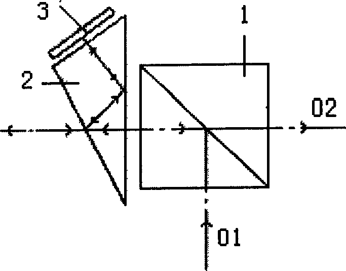
[0043] Such as Figure 5 Shown is a structural example 3 realized by the optical coupler of the present invention. The transparent body 7 is composed of a rectangular prism and an optical glass plate. Wherein, the rectangular prism and the optical glass plate can be the same transparent material, or different transparent materials, and the anisotropic polarization beam splitting medium film 6 of coating can be coated on the inclined surface of the approximately 45 degree angle of the rectangular prism; On the optical glass plate, the size of the rectangular prism and the optical glass plate is determined according to the clear aperture. The situation of the coated anisotropic polarization beam-splitting dielectric film 6 is the same as in Example 1, and the film thickness is 0.25λ 0 , where part of the film thickness is 0.5λ 0 The optical coupler 5 reduces the structure.
PUM
| Property | Measurement | Unit |
|---|---|---|
| Angle of incidence | aaaaa | aaaaa |
Abstract
Description
Claims
Application Information
 - R&D Engineer
- R&D Manager
- IP Professional
- Industry Leading Data Capabilities
- Powerful AI technology
- Patent DNA Extraction
Browse by: Latest US Patents, China's latest patents, Technical Efficacy Thesaurus, Application Domain, Technology Topic.
© 2024 PatSnap. All rights reserved.Legal|Privacy policy|Modern Slavery Act Transparency Statement|Sitemap