
Electrode wire material and solar battery having connection lead formed of the wire material

A technology of solar cells and wires, applied in circuits, welding media, photovoltaic power generation, etc., can solve the problems of connecting wires falling off, poor soldering, insufficient heat conduction, etc., achieve firm connection, not easy to fall off, and improve solderability Effect

Inactive Publication Date: 2006-06-28
PROTERIAL LTD
View PDF2 Cites 9 Cited by
  • Summary
  • Abstract
  • Description
  • Claims
  • Application Information

AI Technical Summary

Problems solved by technology

[0005] However, if Figure 5 As shown, since the middle part of the molten solder plating layer of the electrode wire material is raised in a mountain shape, when the electrode wire material is soldered to the surface electrode of the semiconductor substrate, the solder formed in advance on the surface electrode of the semiconductor substrate in order to conduct the above surface electrode The contact area between the tape and the molten solder coating is reduced, which easily leads to insufficient heat conduction from the semiconductor substrate to the molten solder coating
Therefore, there will be a problem that soldering failure is likely to occur due to lowering of the soldering temperature, and in severe cases, the connecting wire may fall off the semiconductor substrate during the use of the solar cell.

Method used


Image

  • Electrode wire material and solar battery having connection lead formed of the wire material
  • Electrode wire material and solar battery having connection lead formed of the wire material
  • Electrode wire material and solar battery having connection lead formed of the wire material

Examples


Embodiment

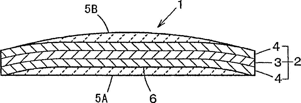
[0041] A cover material (thickness 0.18 mm) in which a 60 μm copper layer was laminated on both surfaces of an intermediate layer made of Invar (Fe-36.5 mass % Ni) and having a thickness of 60 μm was prepared. Using the covering material as a raw material, a strip with a width of 2 mm was produced with a cutter, and the core material of the example with a length of 40 mm was cut from the strip. When cutting, adjust the interval of the rotating blades, such as figure 1 As shown, bending processing was performed to the width direction edge part of a core material, and the cross-sectional shape of the core material was processed into a disk shape. When the cross-sectional shape was observed with an optical microscope (200 times magnification), the maximum depth of the concave portion formed on the concave side of the core material was about 20 μm, and the opening width was about 95% of the core material width. On the other hand, a comparative example core material with a length...


PUM

PropertyMeasurementUnit
melting pointaaaaaaaaaa
coefficient of thermal expansionaaaaaaaaaa

Abstract

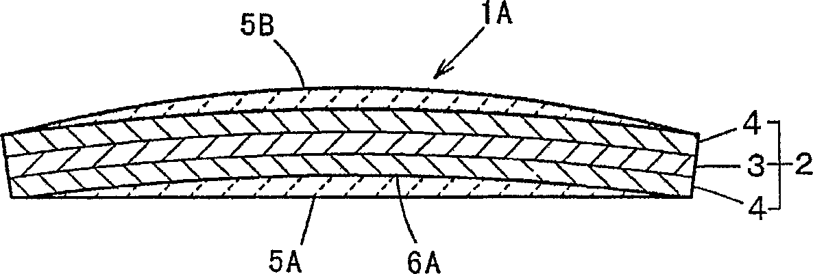
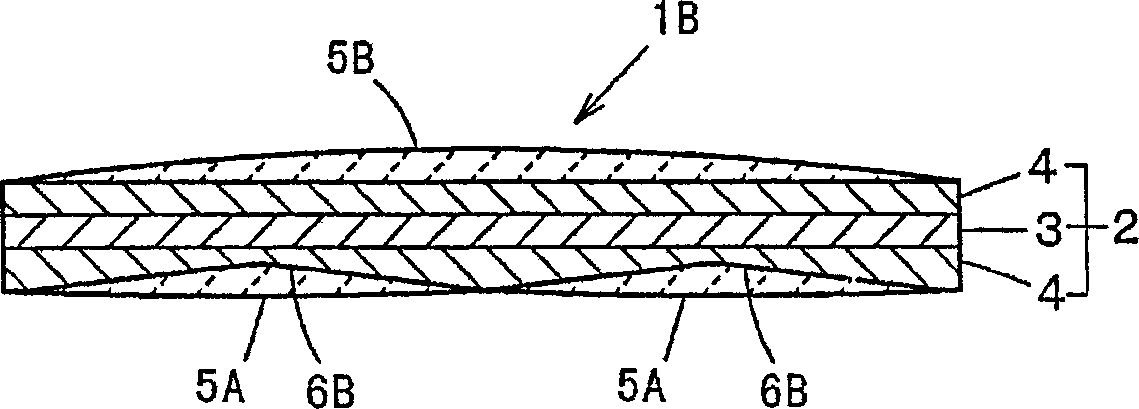
The present invention relates to providing an electrode wire material excellent in solderability that can be produced without using a flat roll or a jointless tape, and a solar cell having a connecting wire for welding the electrode wire material. The electrode wire has a core material (2) formed of a strip-shaped conductive material, and a molten solder plating layer (5A) laminated on the surface of the core material (2). The core material (2) forms a molten solder container along the length direction. With the concave portion (6), the above-mentioned molten solder plating layer (5A) is filled and formed in the above-mentioned concave portion (6). The opening width of the molten solder containing recess (6) in the width direction of the core material is preferably 90% or more of the width of the core material (2). And the above-mentioned core material (2) is preferably made of a clad material formed by laminating the copper layers (4), (4) on both sides of the middle layer (3) formed of a low expansion coefficient Fe alloy.

Description

technical field [0001] The present invention relates to an electrode wire used as a connecting wire for electronic components such as solar cells. Background technique [0002] A solar cell includes a semiconductor substrate formed of a silicon semiconductor having a PN junction, and a plurality of surface electrodes that are linearly provided on the surface of the semiconductor substrate and soldered to connecting wires. In order to obtain a desired electromotive force, a plurality of Solar cells are used in series. A series connection is formed by connecting connecting wires soldered to the surface electrodes of one solar cell to the back electrodes of the other solar cell. [0003] like Figure 5 As shown, the electrode wire prior to the soldering of the above-mentioned connecting wire and the surface electrode of the semiconductor substrate has a core 51 composed of a rectangular copper wire with a circular cross-section and a flat copper wire that is rolled and flatten...

Claims


Application Information

Patent Timeline
Patent Type & Authority Applications(China)
IPC IPC(8): H01L31/04
CPCB23K35/0272B23K35/262B32B15/015C22C13/00C22C38/08H01L31/0508H01L31/0512Y02E10/50H01L31/04H01L31/0224
Inventor 盐见和弘藤田敏明石尾雅昭
Owner PROTERIAL LTD
Learn More