

Substrate treatment equipment and treatment method thereof
A technology for a substrate processing device and a substrate processing method, which is applied in the directions of spraying devices, spraying devices, cleaning methods and utensils, etc., can solve the problems of large size of wet cleaning equipment and harmful health of operators, so as to shorten the stripping and removal time, improve the Safety and effect of improving substrate processing efficiency
- Summary
- Abstract
- Description
- Claims
- Application Information
AI Technical Summary
Problems solved by technology
Method used
Image

Examples
Embodiment 1
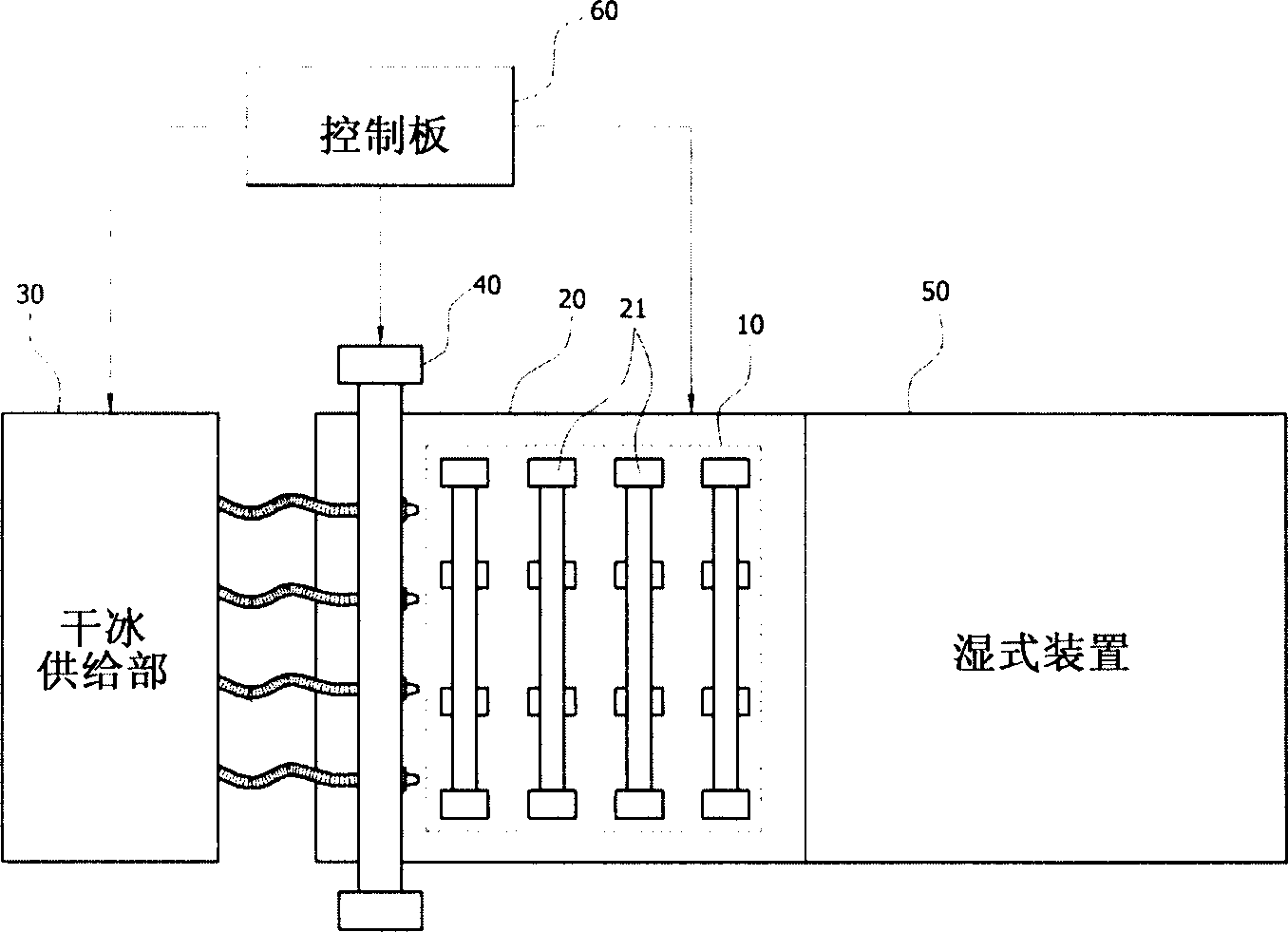
[0031] figure 1 It is a plane configuration diagram of an embodiment of the substrate processing apparatus in the present invention.
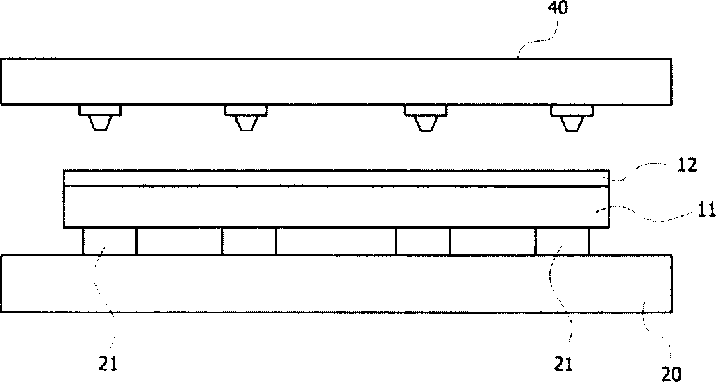
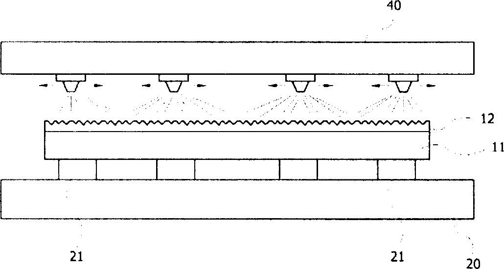
[0032] As shown in the figure, the substrate processing device in the present invention includes: a flat plate 20, provided with a plurality of rollers 21, for loading the substrate 10 that needs to be stripped; a dry ice supply part 30, providing dry ice particles; The entire surface of the removal object film of the substrate on the above-mentioned flat plate 20 is sprayed with dry ice particles provided by the above-mentioned dry ice supply part 30; the wet device 50 performs wet cleaning on the removal target layer of the substrate 10 sprayed by dry ice particles on the above-mentioned flat plate 20; The control board 60 controls the driving of the flat plate 20 , the dry ice supply unit 30 and the spraying device 40 .
[0033] Hereinafter, an embodiment of the substrate processing apparatus of the present invention having the above-mentio...
Embodiment 2
[0063] Figure 4 It is a structural schematic diagram of another embodiment of the substrate processing apparatus of the present invention.
[0064] As shown in the figure, the substrate processing apparatus in the present invention includes: a flat plate 20, provided with a plurality of rollers 21, to load the substrate 10 to be removed; The entire surface is sprayed with dry ice particles; the dry ice particle supply part 31 stores and supplies granular (Pellet) dry ice; the crushing part 32 crushes the granular dry ice provided by the dry ice particle supply part 31 into particles with a particle size of 0.5 to 3.0mm; Spray section 33 sprays the above-mentioned pulverized dry ice particles through the spray pipe of above-mentioned spray device 40; wet device 50 performs wet cleaning on the removal target layer of substrate 10 on the above-mentioned flat plate 20 through dry ice particle spray; exhaust section 70 , to exhaust the debris generated on the above-mentioned flat...
Embodiment 3
[0069] In the above-mentioned Embodiment 1 and Embodiment 2, the dry ice supply part 30 receives solid dry ice from the outside, and sprays the dry ice to the surface of the substrate 10. It is also possible to supply liquid or gaseous carbon dioxide and carrier gas in the dry ice supply part 30 ( Carrier gas), and then change the carbon dioxide into a solid in the nozzle 42 and spray it.
[0070] Figure 5 It is a structural schematic diagram of another embodiment of the substrate processing apparatus in the present invention.
[0071] As shown in the figure, the dry ice supply part 30 in the substrate processing apparatus of the present invention includes: a carbon dioxide supply source 34 and a carrier gas supply source 35 that respectively provide carbon dioxide and a carrier gas; , and provided to the cooling device 36 of the spray pipe 42 of the injection device 40; detect the temperature of the above-mentioned spray pipe 42, and according to the result, the temperature...
PUM
| Property | Measurement | Unit |
|---|---|---|
| Particle size | aaaaa | aaaaa |
Abstract
Description
Claims
Application Information