Screen printing machine and printing method thereof

A screen printing machine, screen printing technology, applied in the direction of screen printing machine, printing machine, rotary printing machine, etc., can solve problems such as bridging defects

Inactive Publication Date: 2006-07-05
DENSO CORP
View PDF1 Cites 21 Cited by
  • Summary
  • Abstract
  • Description
  • Claims
  • Application Information

AI Technical Summary

Problems solved by technology

Unless the solder is properly delivered to the bump formation site, the solder will flow during reflow (since the solder is melted in a non-oxidizing atmosphere to form balls by surface tension) and adjacent bumps will join, causing bridging defect

Method used


Image

  • Screen printing machine and printing method thereof
  • Screen printing machine and printing method thereof
  • Screen printing machine and printing method thereof

Examples


Embodiment Construction

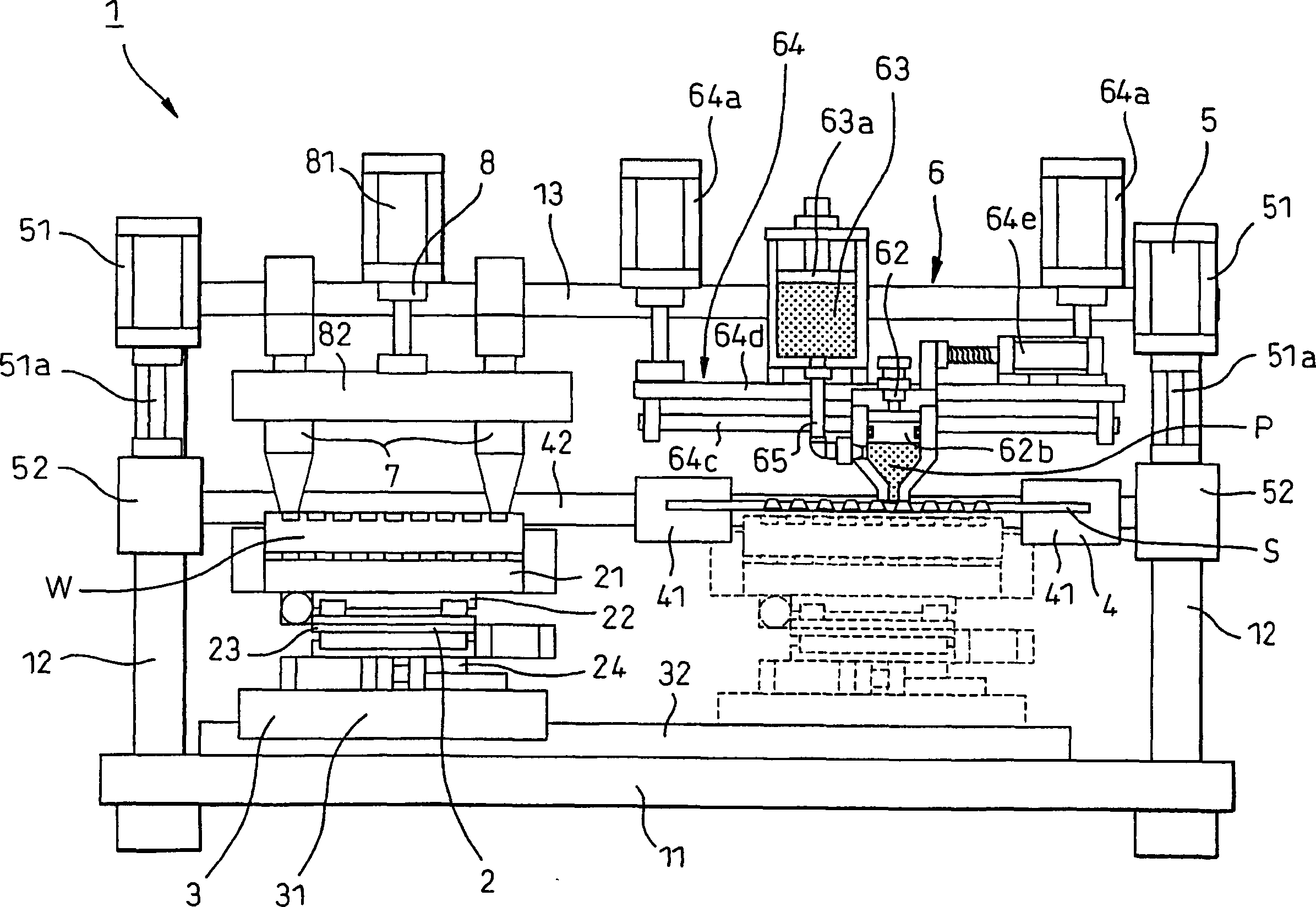
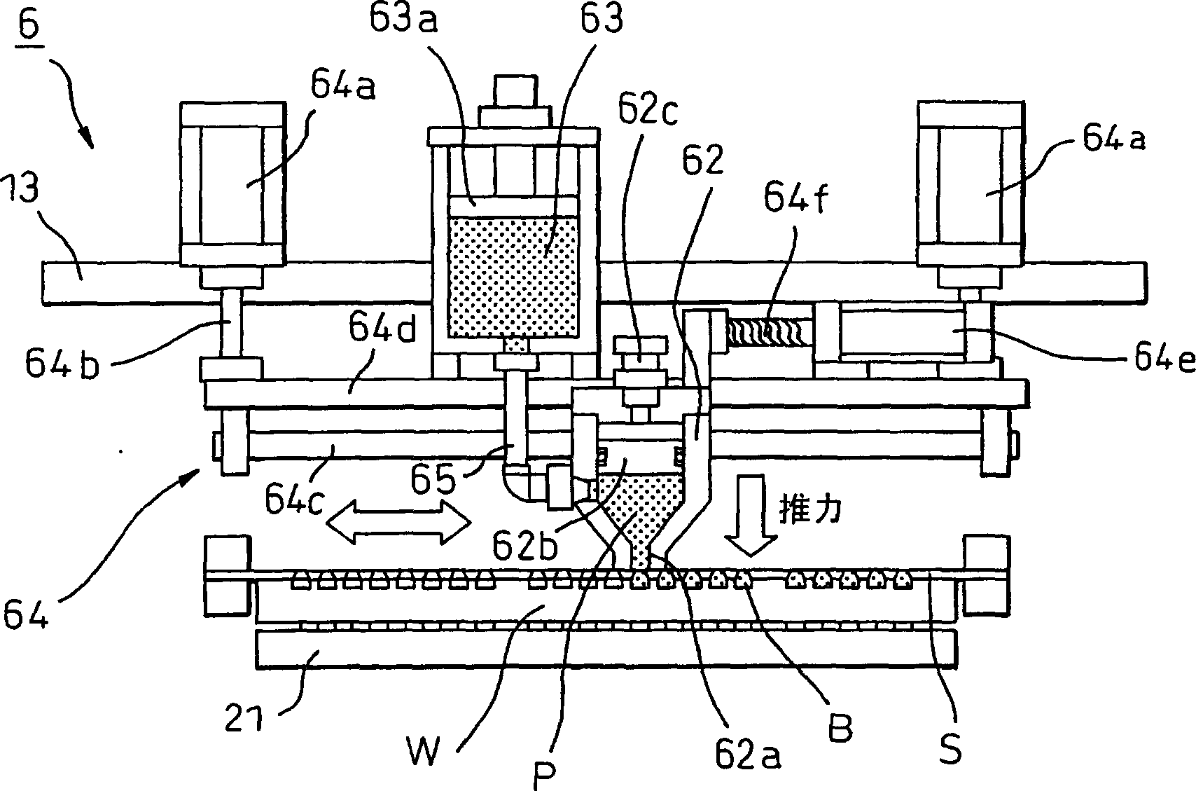
[0025] A screen printing machine and a printing method thereof according to embodiments of the present invention will be explained below with reference to the accompanying drawings. figure 1 is a view showing the overall configuration of the screen printing machine according to this embodiment of the present invention, figure 2 is as figure 1 An enlarged view of the main part of the printing mechanism. The screen printing machine 1 basically includes a workpiece alignment mechanism 2 for positioning a workpiece W as a substrate in X, Y, and θ directions, and a mechanism for linearly moving the workpiece W between a workpiece alignment position and a printing position. The workpiece moving mechanism 3, the screen moving mechanism for linearly moving the screen S (screen cover) between the workpiece alignment position and the printing position 4, the screen lifting mechanism for moving the screen S up and down 5, with A printing mechanism 6 for printing solder paste P onto ...


PUM


Abstract

A printing mechanism (6) of a screen printer (1) for printing a paste (P) through a screen (S) onto a workpiece (W) at a printing position comprising: contacting the screen at a distal end A filling nozzle (62), a filling head (62) into which paste consumed during printing is filled, and a feed box (63) for supplying paste into the filling head. There is an extrusion mechanism (62b, 63a) in each of the filling head and the feed box, and the extrusion pressure of the paste to the screen mask can be controlled. The printing mechanism also includes a filling head support mechanism (64), which can support the filling head in such a way that the filling head can move up and down, and can also adjust the thrust of the filling head on the screen.

Description

technical field [0001] The present invention relates to a screen printing machine and printing method for printing solder paste or the like on a substrate through a screen mask. More particularly, the present invention relates to screen printing machines and printing methods suitable for applying screen printing to high-density multilayer substrates. Background technique [0002] In order to connect a printed substrate and a semiconductor chip, a connection system called a "flip-chip FC bonding system" using solder bumps (tiny solder bumps) is generally used. By arranging semiconductor bumps on a plane, this system can connect thousands of connection points at a time. With the development of information technology, semiconductor chips have higher functions and the connection situation of such semiconductor chips requires smaller size, higher density and larger number of connection points. [0003] In order to form solder bumps, Japanese Unexamined Patent Publication No. 11...

Claims


Application Information

Patent Timeline
Patent Type & Authority Applications(China)
IPC IPC(8): B41F15/40B41F15/08H05K3/12B41F31/08B41F31/28
CPCB41M1/12B41F15/42H05K2203/0126H05K3/1233B41F15/08B41F15/00
Inventor 坂井田敦资郷古伦央谷口敏尚都筑勇二
Owner DENSO CORP
Why Eureka
Try Eureka