Exhaust gas purifier

一种排气净化装置、收集室的技术,应用在排气装置、消音装置、胶体化学等方向,能够解决流路阻力增大等问题,达到实现外加电压的降低、收集面积扩大、提高去除效率的效果

Inactive Publication Date: 2006-07-05
HINO MOTORS LTD
View PDF1 Cites 17 Cited by
  • Summary
  • Abstract
  • Description
  • Claims
  • Application Information

AI Technical Summary

Problems solved by technology

[0016] However, if the two electrodes are extended in the exhaust gas flow direction, the flow path resistance will increase, and if the distance between the two electrodes is increased, the discharge plasma will not be generated unless the applied voltage is further increased.

Method used


Image

  • Exhaust gas purifier
  • Exhaust gas purifier
  • Exhaust gas purifier

Examples


Embodiment 1

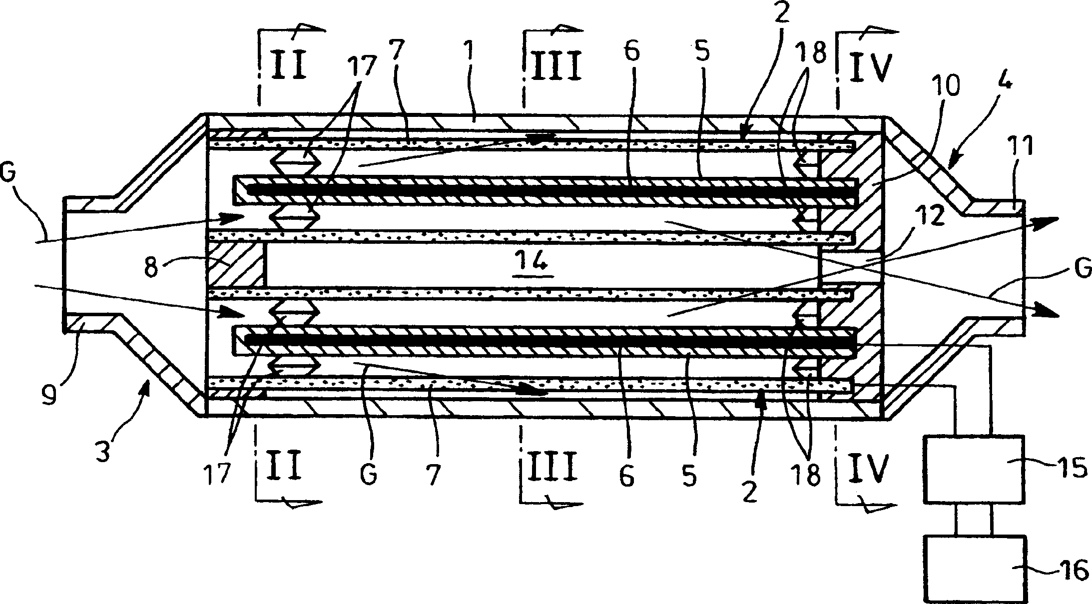
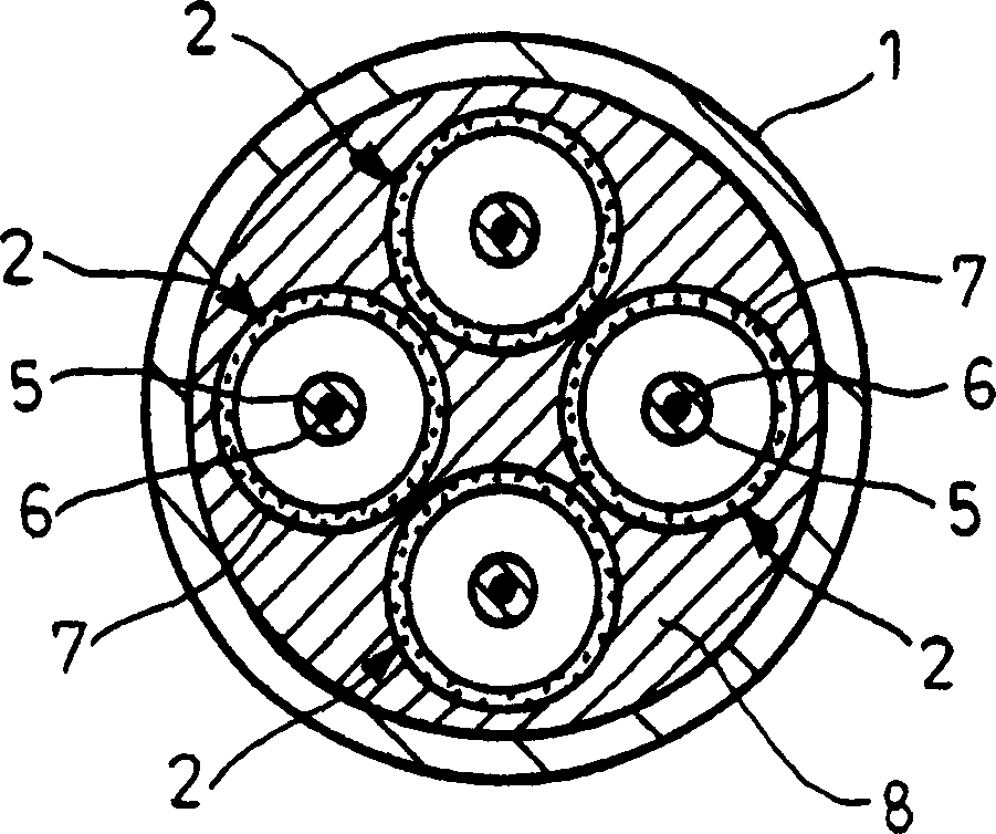
[0058] Figure 1 to Figure 4 The first embodiment of the exhaust purification device of the present invention is shown. This exhaust purification device has a plurality of collection chambers 2 arranged side by side inside a cylindrical casing 1, and an exhaust gas distribution is provided at one end of the casing 1. The mechanism 3 is provided with an exhaust collecting mechanism 4 at the other end of the housing 1.

[0059] The collection chamber 2 has a structure in which a rod-shaped inner electrode 6 whose outer surface is covered with a dielectric material 5 such as ceramics is coaxially arranged inside a cylindrical outer electrode 7 made of a conductive filter that can collect particles.

[0060] As the above-mentioned conductive filter, there is a form in which fibrous metals are laminated and sintered to be integrated, a form in which a sintered body of metal powder and a fine metal mesh are laminated and sintered, or by Sintering is a form in which metal powder is plac...

Embodiment 2

[0076] Figure 5 to Figure 8 The second embodiment of the exhaust purification device of the present invention is shown. This exhaust purification device has a plurality of collection chambers 22 arranged side by side inside a cylindrical casing 21, and an exhaust gas distribution is provided at one end of the casing 21 The mechanism 23 is provided with an exhaust collecting mechanism 24 at the other end of the housing 21.

[0077] The collection chamber 22 has a structure in which a cylindrical outer electrode 27 composed of a conductive filter capable of collecting particulates is coaxially arranged inside a cylindrical outer electrode 26 whose inner surface is covered with a dielectric material 25 such as ceramics.

[0078] The exhaust distribution mechanism 23 is composed of a support plate 28, a plunger 29, and an inlet 30. The support plate 28 is closely attached to the entire outer surface of one end of the outer electrode 26 of each collection chamber 22, and is closely a...

Embodiment 3

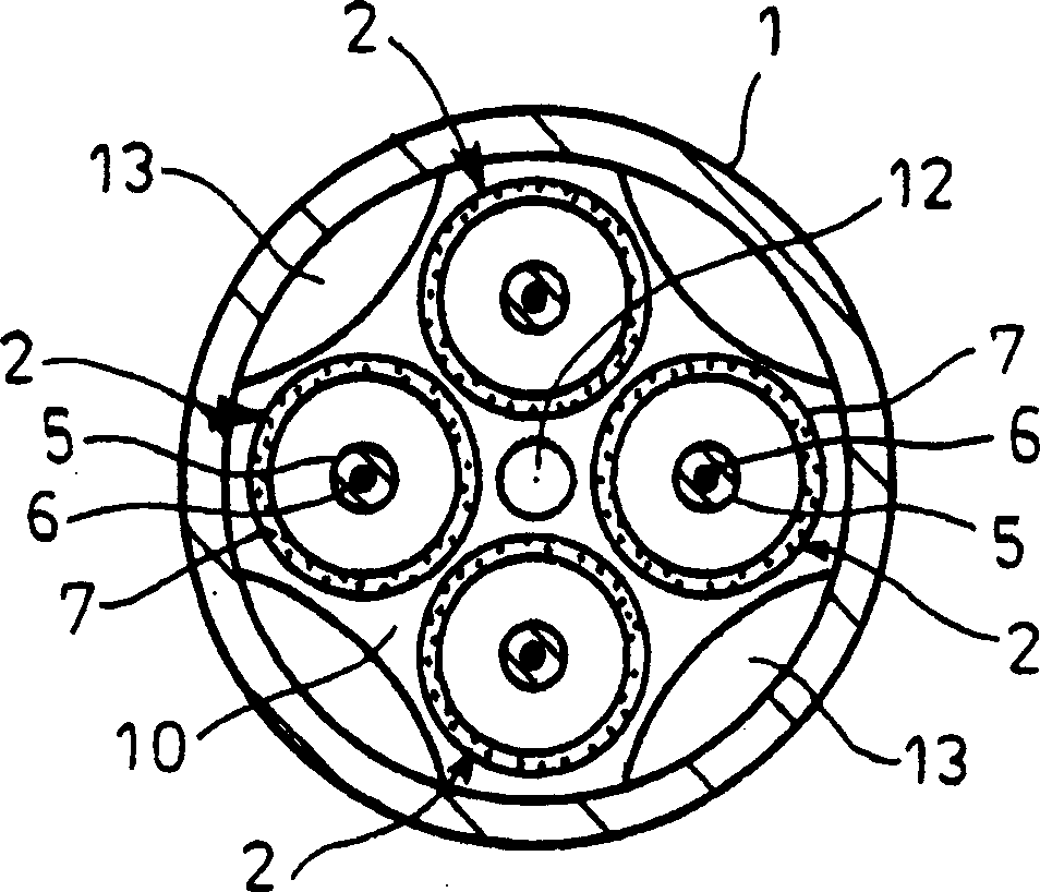
[0089] Figure 9 to Figure 12 The third embodiment of the exhaust purification device of the present invention is shown. This exhaust purification device has a plurality of collection chambers 42 arranged side by side inside a cylindrical casing 41, and an exhaust gas distribution is provided at one end of the casing 41 The mechanism 43 is provided with an exhaust collecting mechanism 44 at the other end of the housing 41.

[0090] The collection chamber 42 has a cylindrical dielectric 46 coaxially arranged inside a cylindrical outer electrode 45 composed of a conductive filter that can collect particles, and a cylindrical shape composed of a conductive filter that can collect particles The inner electrode 47 is coaxially arranged inside the dielectric body 46 described above.

[0091] The exhaust distribution mechanism 43 is composed of a support plate 48, a plunger 49, and an inlet 50. The support plate 48 is closely attached to the entire outer surface of one end of the outer e...


PUM


Abstract

A cylindrical outer electrode (7) capable of collecting particulates is provided with a collecting cell (2) having passed through an inner electrode (6) whose outer surface is covered with a dielectric (5). The collecting cell (2) is disposed inside a cylindrical housing (1). An exhaust gas distributing means (3) is disposed at one end of the housing (1) for introducing exhaust gases (G) into the interior of the outer electrode of each collecting cell (2), and an exhaust gas collecting means (4) is disposed at the other end of the housing so that the means (4) communicates with a gap (14) between the inner surface of the housing and the outer surface of the outer electrode (7) of each collecting cell (2). An electric discharge control unit (15) is connected to the inner and outer electrodes (6, 7). Thus, an exhaust gas purifier, which is high in particulate removal efficiency and easy to maintain, is obtained.

Description

Technical field [0001] The invention relates to an exhaust gas purification device. Background technique [0002] The exhaust gas of diesel engines (combustion gas of diesel) contains coal composed of carbon and SOF (Soluble Organic Fraction) composed of high-boiling hydrocarbon components as the main components, and a trace amount of sulfuric acid is added. Particulate Matter (Particulate Matter: particulate matter) composed of salt (mist-like sulfuric acid component). [0003] In order to suppress the diffusion of such particles into the atmosphere, a filter for collecting the particles is often installed in the exhaust system of the engine. [0004] As an example of such a particulate filter, there is a form in which a honeycomb mandrel is formed by ceramics such as cordierite, and engine exhaust gas flows through a plurality of passages divided by the porous thin wall of the honeycomb mandrel. [0005] In the above-mentioned particulate filter, every other end portion of the ...

Claims


Application Information

Patent Timeline
Patent Type & Authority Applications(China)
IPC IPC(8): F01N3/02B01D39/20B01D46/42B01J19/08F01N3/01F01N3/08
CPCF01N3/01B03C3/49B03C3/363B03C2201/30B03C3/366Y02T10/20Y10S55/30Y10S55/10Y10S55/38Y02T10/12B01D46/00B01D53/00F01N3/02
Inventor 古川卓俊竹中嘉英町田耕一
Owner HINO MOTORS LTD
Why Eureka
Try Eureka