Phototherapeutic device

A light therapy and light source technology, applied in light therapy and other directions, can solve the problems of difficult treatment, easy fatigue of doctors, affecting the treatment effect, etc., and achieve the effect of the best treatment effect.

Inactive Publication Date: 2006-07-12
IND TECH RES INST
View PDF0 Cites 9 Cited by
  • Summary
  • Abstract
  • Description
  • Claims
  • Application Information

AI Technical Summary

Problems solved by technology

[0003] However, in the application of oral cancer, the current LED light source still has considerable problems
The main reason is that some oral cancer patients are difficult to open their mouths for treatment due to the massive proliferation of oral cancer tissues, and the light guide tube of the light source is not easy to enter the patient's mouth for irradiation, and cannot fully irradiate the lesions in the oral cavity, resulting in difficulties in treatment
[0004] At the same time, the known treatment method is that the doctor needs to hold the light guide device in one hand and treat the patient with the other hand. The doctor is prone to fatigue, and the patient is prone to drooling when he opens his mouth for a long time, diluting the photosensitive material and affecting the treatment effect.

Method used


Image

  • Phototherapeutic device
  • Phototherapeutic device
  • Phototherapeutic device

Examples


no. 1 example

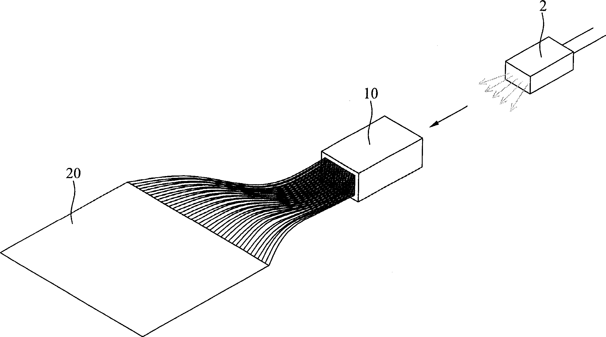
[0027] figure 1 It is a schematic diagram of a preferred embodiment of the phototherapy device of the present invention. The light emitted by a light source 2 is transmitted to a flexible optical fiber fabric (light guide) 20 through a light coupling device 10 .

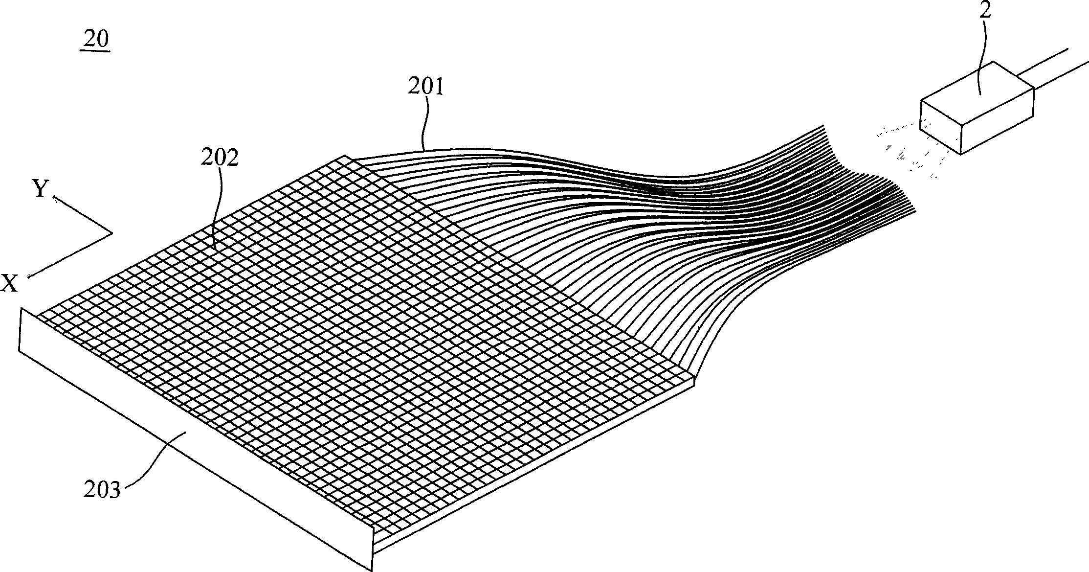
[0028] figure 2 It is an enlarged view of the optical fiber fabric 20 of the present invention. The optical fiber fabric 20 is formed by blending and weaving several optical fibers 201 and silk threads 202 for weaving. The optical fiber 201 extends in the x direction, while the textile thread extends in the y direction.

[0029] Generally speaking, the surface of the optical fiber 201 is covered with a layer of light-shielding material so that light cannot escape from the side of the optical fiber 201 . However, in the present invention, since it is desired that the light is emitted from the side of the optical fiber 201, the light-shielding material of part of the optical fiber 201 is selectively removed. , an...

no. 2 example

[0034] Figure 4a , 4b It is a schematic diagram of another embodiment of the present invention. Wherein, an organic light emitting diode layer (OLED) 40 is arranged on a transparent substrate 100 as a light source, a metal electrode 401 is arranged above the organic light emitting diode layer 40, and a metal electrode 401 is arranged between the bottom of the organic light emitting diode layer 40 and the transparent substrate 100. There is a transparent electrode 402, whereby the OLED layer 40 can emit light. Since all the above-mentioned components are flexible, they can be deformed according to the shape of the affected part.

[0035] However, the difference between this embodiment and the first embodiment is that the light source of this embodiment is disposed in the flexible optical component, so it can emit light by itself without introducing light from an external light source.

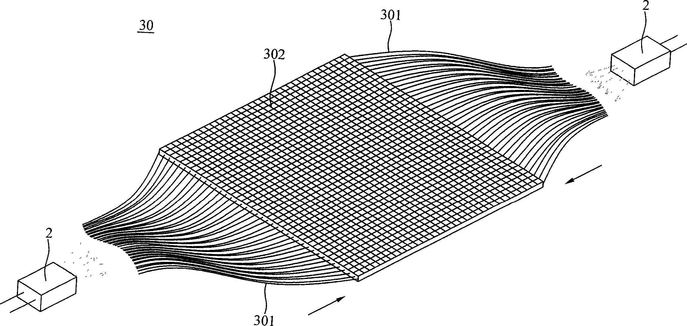
[0036] Figure 5 express figure 2 Schematic illustration of the fiber optic fabric us...


PUM


Abstract

The invention relates to a phototherapy device, comprising a stiff in flexure optical component, which can change shape according to the disease part size and provides a light with a special wavelength to irradiate the disease part for treatment. The stiff in flexure fiber-optical textile in this invention treats the disease part of different shape, which can even be put into the deep mouth cavity, and the therapeutic light emitted by fiber-optical textile is distributed horizontally, for which the disease part of large size can be treated with uniform therapeutic light and be treated with a good effect.

Description

technical field [0001] The present invention relates to a phototherapy device, in particular to a flexible optical component, which can be deformed according to the shape of the affected part to be treated, and provides light of a specific wavelength to irradiate the affected part to provide treat. Background technique [0002] In recent years, due to the large increase in the number of people chewing betel nuts, the prevalence of oral cancer has been increasing year by year. Traditionally, the treatment of oral cancer is mainly based on surgical resection, supplemented by radiation therapy and chemotherapy. This type of invasive treatment often causes serious problems for patients in speech, chewing, swallowing and even loss of taste. Therefore, it is necessary to develop a set of treatment methods different from traditional ones. The so-called photodynamic therapy (Photodynamic therapy, generally abbreviated as PDT) is the use of light-sensitive substances to cause cell ...

Claims


Application Information

Patent Timeline
Patent Type & Authority Applications(China)
IPC IPC(8): A61N5/06
Inventor 黄胜邦李明一殷尚彬王君伟许毅芝许荣宗
Owner IND TECH RES INST
Why Eureka
Try Eureka