Supercharge Your Innovation With Domain-Expert AI Agents!

Wind-driven hydraulic plunger water raising method and apparatus

A hydraulic column and pneumatic technology, applied in the field of pneumatic hydraulic plunger pumping method and device, can solve the problems of low work efficiency, small head, large investment, etc., and achieve high work efficiency, high water delivery pressure, and water delivery flow big effect

Inactive Publication Date: 2006-07-12
丛阳滋
View PDF0 Cites 3 Cited by
  • Summary
  • Abstract
  • Description
  • Claims
  • Application Information

AI Technical Summary

Problems solved by technology

[0002] We know that people use wind energy mainly to generate electricity, which is composed of wind blades, transmission shafts, wind direction adjustment pieces, brackets and power generation devices. Using the wind to drive the cup rubber ring to lift water, these ancient methods have small head, huge equipment, limited flow, low work efficiency, difficult to realize industrial production, and need to avoid strong winds, which cannot solve the problem of long-distance large-flow high-pressure water delivery; One method is to connect two water storage tanks, one is filled with water, and the air in the unfilled water storage tank is driven by the wind to compress the air in the water storage tank to compress the water. The disadvantage is that the equipment investment is large and the efficiency is low. The scope of application is narrow; there are many existing pumping equipment, such as centrifugal, axial flow and mixed flow pumps, which use electricity as the power source, and the disadvantages are waste of energy and limited use conditions. It is a plunger type pumping equipment. I invented a "piston vacuum direct pressure double diaphragm liquid high pressure pump" on June 1, 2003. The patent number is 03268408. It "has a pump body, an eccentric shaft, a piston, a seal Ring, connecting rod, liquid chamber, liquid suction one-way valve, liquid discharge one-way valve, the piston moves up and down through the rotation of the eccentric shaft, one side of the liquid chamber is provided with a liquid suction one-way valve, and the top is provided with a liquid discharge one-way valve, It is characterized in that there is a high-pressure air chamber on the top of the pump body, a high-pressure liquid chamber below the high-pressure air chamber, a low-pressure liquid chamber below the high-pressure liquid chamber, and a liquid discharge check valve connected between the low-pressure liquid chamber and the high-pressure liquid chamber. There is a liquid-gas diaphragm between the air chamber and the high-pressure liquid chamber, and an oil-liquid diaphragm in the low-pressure liquid chamber
"It can be driven by motors, engines, etc. After use, because the oil diaphragm is directly connected to the top of the piston, the service life of the oil diaphragm is short, and there are also disadvantages such as complex structure and high production cost.

Method used


Image

  • Wind-driven hydraulic plunger water raising method and apparatus
  • Wind-driven hydraulic plunger water raising method and apparatus

Examples


Embodiment Construction

[0014] The present invention will be further described below in conjunction with accompanying drawing:

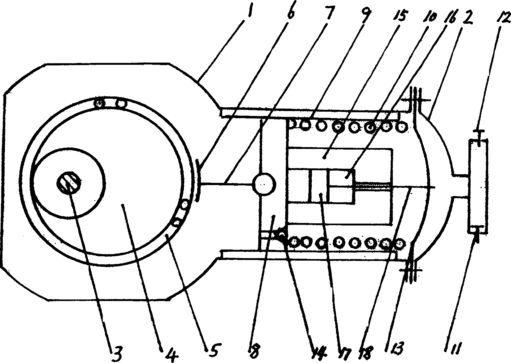
[0015] A pneumatic hydraulic plunger pumping method is as follows: using wind energy to drive the wind blades to rotate to generate power, the power changes the transmission direction through the transmission shaft and the transmission, and then the output shaft passes through the automatic clutch device, the universal adjustment shaft and the hydraulic plunger diaphragm pumping method. The input shaft of the pump is connected, and the hydraulic plunger diaphragm pump pumps water.

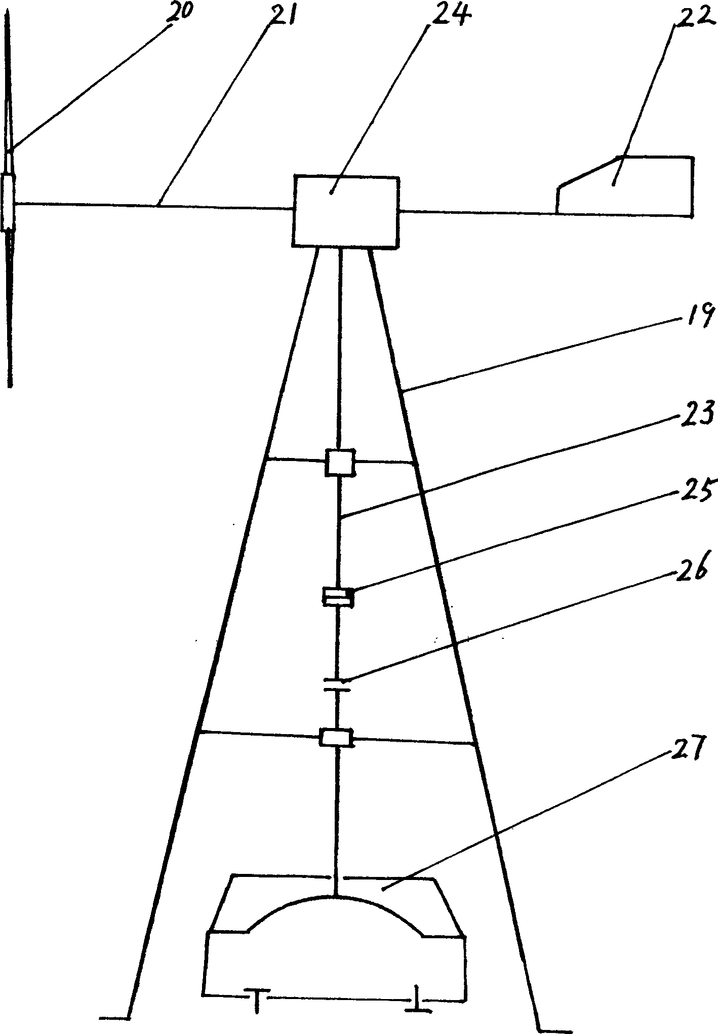
[0016] A wind-driven hydraulic plunger pumping device is composed of a wind energy conversion mechanism and a hydraulic plunger diaphragm type water pump. The wind energy conversion mechanism is provided with a support frame 19, fan blades 20, a transmission shaft 21, a wind direction adjustment piece 22, a support frame 19, The structure of wind blade 20, power transmission shaft 21, wind direc...


PUM


Abstract

The invention discloses a wind hydraulic plunger piston water-lifting method and relative device, which uses wind energy to drive the transmission axle and speed-changer to be changed direction and connected to the input axle of hydraulic plunger piston water-lifting device to lift water. It is characterized in that: the transmission axle whose power is changed by speed-changer is connected to the input axle via the output axle; the periphery of separation film is connected to the machine body and machine cover; and plunger piston has a hydraulic oil channel, and a single valve. The invention can utilize wind energy to feed water with high pressure, high efficiency, large flux, lower noise, simple structure, easy maintenance and long service life, which can apply variable areas as farm irrigation and urban afforestation, etc.

Description

Technical field: [0001] The invention relates to a liquid conveying device, in particular to a method and device for pumping water with a pneumatic hydraulic plunger. Background technique: [0002] We know that people use wind energy mainly to generate electricity, which is composed of wind blades, transmission shafts, wind direction adjustment pieces, brackets and power generation devices. Using the wind to drive the cup rubber ring to lift water, these ancient methods have small head, huge equipment, limited flow, low work efficiency, difficult to realize industrial production, and need to avoid strong winds, which cannot solve the problem of long-distance large-flow high-pressure water delivery; One method is to connect two water storage tanks, one is filled with water, and the air in the unfilled water storage tank is driven by the wind to compress the air in the water storage tank to compress the water. The disadvantage is that the equipment investment is large and the ...

Claims


Application Information

Patent Timeline
Patent Type & Authority Applications(China)
IPC IPC(8): F04B43/06F03D9/00F03D9/28
CPCY02E10/72
Inventor 丛阳滋丛培楠
Owner 丛阳滋
Features
  • R&D
  • Intellectual Property
  • Life Sciences
  • Materials
  • Tech Scout
  • Unparalleled Data Quality
  • Higher Quality Content
  • 60% Fewer Hallucinations
Learn More