Chlorine leakage absorption device and method

An absorption device and chlorine release technology, which is applied in separation methods, chemical instruments and methods, and separation of dispersed particles, can solve the problems of large floor area, low absorption efficiency, and many pipelines, and achieve reduced floor space and high reaction efficiency. Improvement, the effect that the absorption reaction is sufficient

Inactive Publication Date: 2006-07-19
刘树伟
View PDF1 Cites 3 Cited by
  • Summary
  • Abstract
  • Description
  • Claims
  • Application Information

AI Technical Summary

Problems solved by technology

[0005] But the device proposed in this patent also has many shortcomings in actual use
One of its typical characteristics is that all the reactants involved in the reaction flow in various pipelines except iron filings, which results in many pipelines, complex equipment, and large floor space, which increases the cost and is not conducive to popularization and utilization.
Moreover, the material for reducing fer

Method used


Image

  • Chlorine leakage absorption device and method
  • Chlorine leakage absorption device and method
  • Chlorine leakage absorption device and method

Examples


Embodiment 1

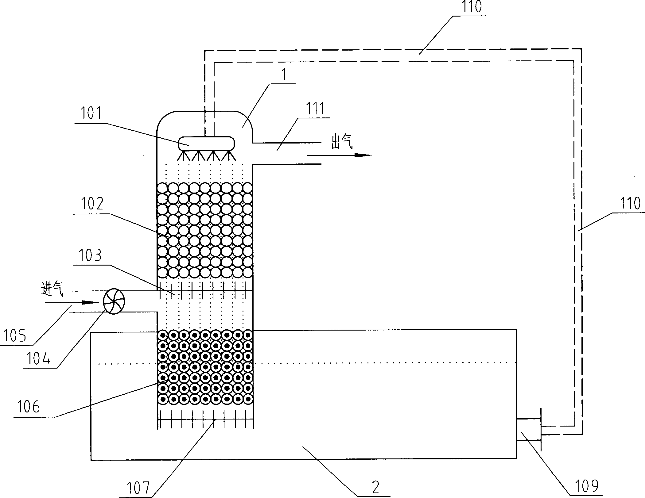
[0029] like figure 1 As shown, the chlorine release absorption device includes a blower 104 , a chlorine delivery pipe 105 , a reaction tower 1 , a liquid storage tank 2 , an acid-resistant pump 109 and a delivery pipe 110 .

[0030] Wherein, one end of the blower 104 passes through the chlorine delivery pipe 105 and imports the chlorine discharge to be absorbed (generally from the chlorination room, not shown in the figure), and the other end of the blower 104 passes through the chlorine delivery pipe 105 and the air inlet of the reaction tower 1 Connected; Reaction tower 1 comprises spraying device 101, chlorine reaction absorption layer 102, dividing plate 103 (for isolation between the upper and lower layers), ferric chloride replacement reaction layer (106) and filter grid successively from top to bottom (107), the chlorine reaction absorbing layer 102 is positioned on the reaction tower inlet, and the shower device 101 is positioned at the chlorine reaction absorbing lay...

Embodiment 2

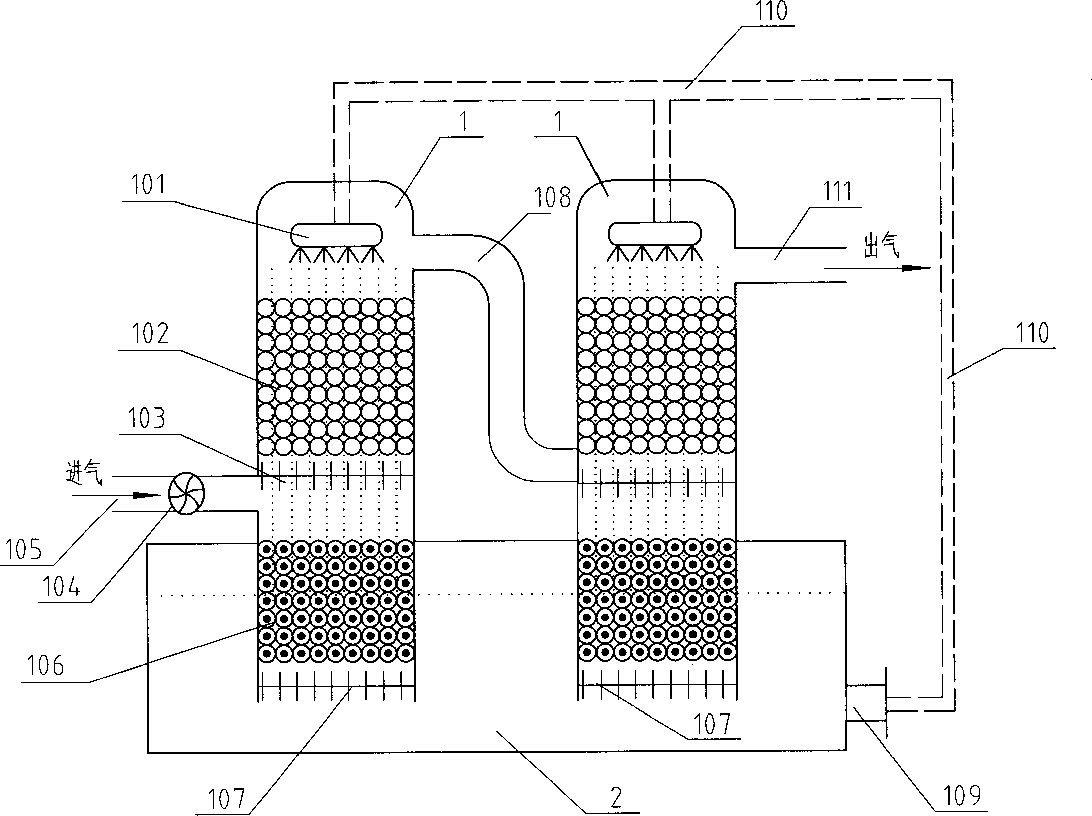
[0039] like figure 2 As shown, in order to increase the absorption rate of chlorine, on the basis of embodiment one, a next-level reaction tower and a chlorine delivery connecting pipe 108 are added, and one end of the chlorine delivery connecting pipe 108 is connected to the gas outlet of the upper-level reaction tower, and the chlorine delivery The other end of the connecting pipe 108 is connected to the air inlet of the next-stage reaction tower. The interior setting of the next-stage reaction tower is the same as that of the reaction tower. The spray device of the first-stage reaction tower is connected with the outlet of the ferrous chloride infusion pipe, and the lower part of the next-stage reaction tower is placed in the liquid storage tank 2 and communicated with the liquid storage tank 2.

[0040] Working process, the difference with embodiment one is:

[0041] The air containing chlorine enters the next reaction tower from the gas outlet of the reaction tower thro...

Embodiment 3

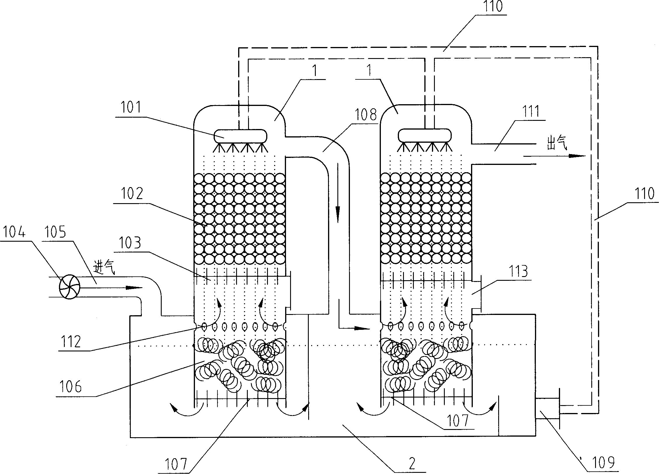
[0044] like image 3 As shown, this embodiment has been improved on the basis of embodiment two, mainly:

[0045] First, the chlorine delivery pipe 105 is not directly connected to the reaction tower, but is connected to the opening on the upper part of the liquid storage tank 2, and chlorine gas is sent into the cavity inside the liquid storage tank and above the liquid level; correspondingly, in the The part of the reaction tower 1 protruding into the liquid storage tank and above the liquid level is provided with an air intake guide hole 112 . In this way, the scheme of pressing chlorine gas into the upper cavity of the liquid storage tank first, and then entering the reaction absorption layer through the air guide hole in the middle of the reaction tower can buffer and homogenize the rising momentum of chlorine gas, thereby making the absorption reaction more sufficient.

[0046] Second, a feeding port 113 is provided in the middle of the reaction tower 1, which is conven...


PUM


Abstract

The invention discloses an absorbing device and method of leaked chlorine, which comprises the following parts: reaction tower, chlorine transmission pipe, aerator, ferric dichloride spout, acid-resisting pump and reservoir, wherein the reaction tower contains spray device, chlorine reaction absorption layer, escape pipe and reaction layer in the rear part of reaction tower; the reservoir connects the other end of ferric dichloride spout; the bottom of reaction tower extends in the reservoir. The method comprises the following steps: forcing the ferric dichloride into the replacement reaction layer by itself gravity; producing iron chloride; making the solution pierce the replacement reaction layer; circulating the solution in the reservoir under the reaction tower. The invention saves the absorber reaction tank and iron trichloride outlet pipe, which places the reaction part of ferric dichloride and iron under the bottom of reaction tower directly.

Description

technical field [0001] The invention relates to a chlorine leakage absorption device and method. Background technique [0002] Chlorine leakage absorption is an important process in modern factories, especially water treatment plants. If it is not handled properly, it will easily cause environmental pollution, and if the design of the process flow and equipment is unreasonable, it will increase the cost, which is extremely unfavorable for large-scale industrial production. [0003] At present, the most common chlorine release absorption device is to use sodium hydroxide for absorption. However, due to the strong corrosiveness of sodium hydroxide, the requirements for equipment are relatively high, and equipment needs to be overhauled frequently. Moreover, its absorption liquid will continue to decrease during use and needs to be added regularly, which will also cause an increase in cost. [0004] For this reason, someone proposes to use ferrous chloride solution as absorbe...

Claims


Application Information

Patent Timeline
IPC IPC(8): B01D53/18B01D53/68B01D53/78
Inventor 刘树伟
Owner 刘树伟
Why Eureka
Try Eureka