
Beam forming network with continuously variable differential phase

A differential phase and variable technology, applied to waveguide devices, antennas, circuits, etc., can solve the problems of limited practical application, inconvenient processing, and complexity, and achieve suppression of passive intermodulation products, low cost, and small size Effect

Active Publication Date: 2006-07-19
COMBA TELECOM TECH (GUANGZHOU) CO LTD
View PDF2 Cites 30 Cited by
  • Summary
  • Abstract
  • Description
  • Claims
  • Application Information

AI Technical Summary

Problems solved by technology

It can be seen that in this example, two "U"-shaped phase shifters are used, correspondingly 54b and 54c or 58 and 59 need to be integrally processed, and the hollow ring cross section obviously brings inconvenience to the processing
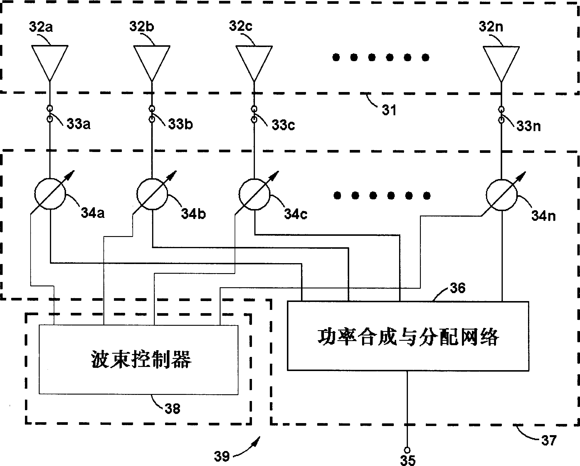
[0014] In addition, for the electrical downtilt base station antenna composed of n-way radiating antenna elements, the continuous adjustment of the beam requires a beamforming network composed of at least n-1 phase shifter elements, and generates a series of differential phases Δ, 2Δ, .. ., (n-1)Δ, so, if there are multiple phase shifter size structures due to different phase shifting ranges or if multiple complex mechanical transmissions are used, it will limit its practicality due to its complexity and high cost application

Method used


Image

  • Beam forming network with continuously variable differential phase
  • Beam forming network with continuously variable differential phase
  • Beam forming network with continuously variable differential phase

Examples


no. 1 example

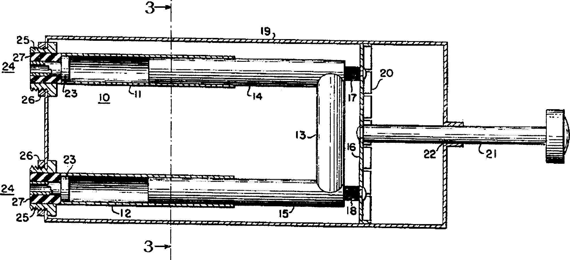
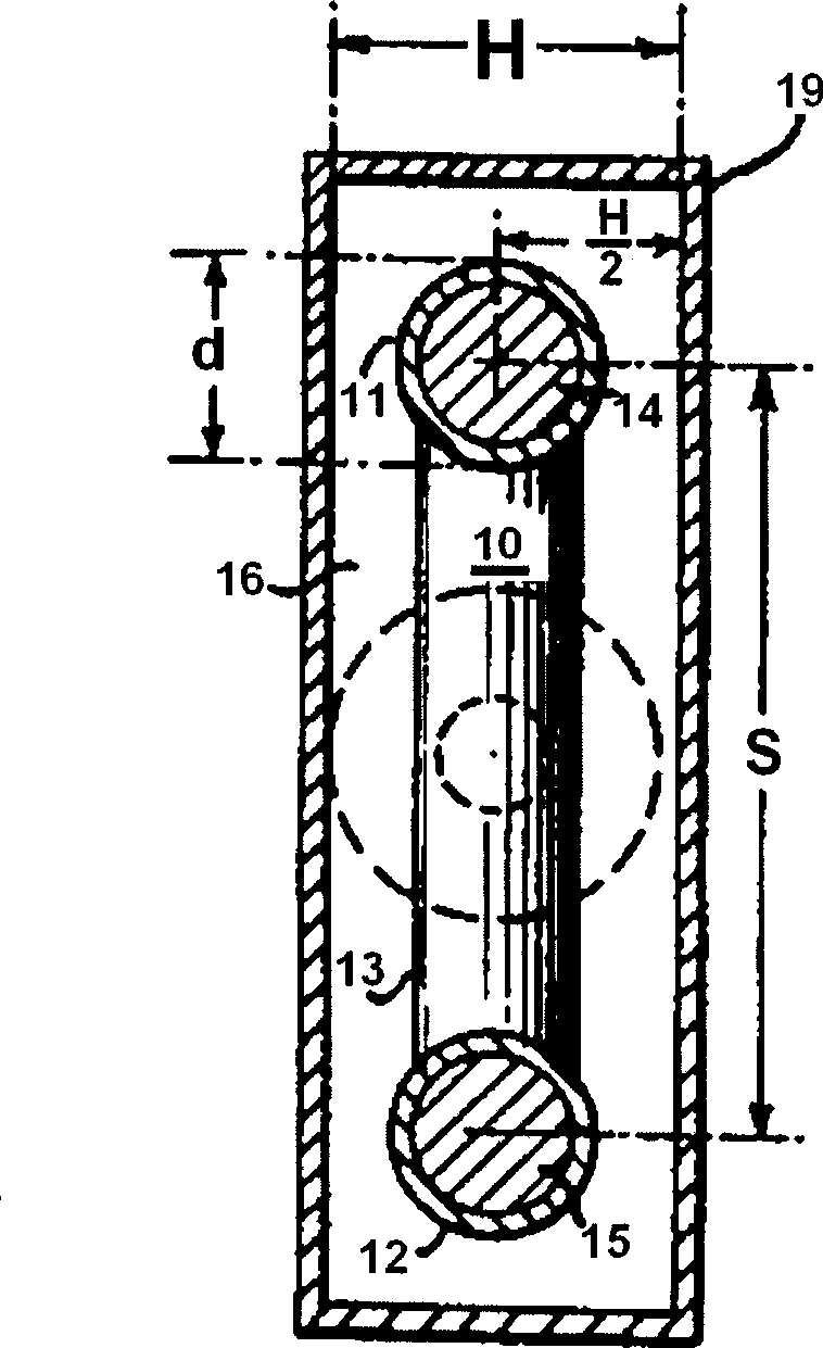
[0043] see Figure 6 and Figure 7 In the present invention, the differential phase continuously variable beamforming network 70 is integrally designed inside the metal cavity 108 . These include:

[0044] A power splitter group consisting of 4 power splitters, that is, a front power splitter 71, a main power splitter 72, and a slave power splitter 73, 74; 4 phase shifters 81, 82, 83, 84; an insulator 111; a dielectric rod 110; 6 external ports 60, 61, 62, 63, 64, 65.

[0045] In the power splitter group, the pre-power splitter 71 is made up of striplines 221, 222, 223, the stripline 221 is used as a synthesis end, the striplines 222, 223 are used as an output end, and the signal distribution of the stripline 221 To the output of the two arms of the striplines 222, 223, as we all know, the respective length and width of the striplines 221, 222, 223 determine the required power distribution ratio, and also determine the impedance matching characteristics on a specific workin...

no. 2 example

[0074] see Figure 10 The improvement of the second embodiment relative to the first embodiment is that: the strip line 221 at the synthesis end of the main power splitter 72 is directly electrically connected with the power synthesis end 601 through a coaxial wire, and the pre-power splitter is discarded. Correspondingly, there are only four power distribution ports left, which are 61, 62, 64, and 65 respectively. In this way, according to the description of the above-mentioned first embodiment, it can be similarly obtained that the differential phases from the power combining terminal 601 to the four power distribution terminals 61, 62, 64, and 65 are -2Δ, -Δ, +Δ, +2Δ in sequence, combining Another pre-power splitter 71 (not shown, refer to Figure 7 ) The 0 differential phase output of the power distribution terminal can also obtain 5 phase shift outputs with differential phases of -2Δ, -Δ, 0, +Δ, +2Δ in sequence. In this way, the original pre-power divider 71 inside the ...


PUM


Abstract

The invention relates to a wave beam construction network with continuous variable differential phase, which comprises: a metallic chamber which contains power divider and several phase shifters. Wherein, said power divider comprises a main power divider and several sub power divider. Each phase shifter is distributed at two sides inside the metallic chamber according to the different direction of phase shift; a insulator is arranged between them connecting each phase shifter; the insulator is connected to a medium rod; the metallic chamber has a operation hole for operating said medium rod. The invention can be constructed integrated, while it can realize phase shift and the power amplitude weighting, with simple structure, small volume, simple producing process and lower cost. In addition, the metals of movable and fixed parts of phase shifter use untouched capacitor coupling signal transmission to restrain the passive product and the high power fire strike.

Description

【Technical field】 [0001] The invention relates to a beam forming network, in particular to a beam forming network with continuously variable differential phases used for base station antennas of a cellular mobile communication system. 【technical background】 [0002] Base station antennas are key components of digital cellular mobile communication systems. The base station antenna provides wireless signal coverage to the cell (referred to as the service cell) where it is located; at the same time, it suppresses the wireless interference (referred to as the same frequency interference) from other remote cells with the same operating frequency (referred to as the same frequency cell). The method to realize the above functions is to rationally adjust the beam pointing of the vertical plane pattern of the base station antenna so that the pointing angle is properly tilted downward in the horizontal direction (also called beam downtilt). Since in many complex practical application...

Claims


Application Information

Patent Timeline
IPC IPC(8): H01Q3/36H01P1/18
CPCH01P1/18H01Q3/30
Inventor 卜斌龙薛锋章孙善球谢国庆范颂东
Owner COMBA TELECOM TECH (GUANGZHOU) CO LTD
Learn More