
Magnetic resonance imaging apparatus

A technology of magnetic resonance imaging and ferromagnets, applied in magnetic resonance measurement, measuring devices, measuring magnetic variables, etc., can solve problems such as inappropriateness, limited number of people, and long distances, and achieve the effect of improving openness and proximity

Inactive Publication Date: 2006-07-26
HITACHI MEDICAL CORP
View PDF3 Cites 3 Cited by
  • Summary
  • Abstract
  • Description
  • Claims
  • Application Information

AI Technical Summary

Problems solved by technology

Thereby, also can produce the situation that carries out IVR operation with inappropriate posture
In addition, the number of people is also limited to some extent
[0008] In addition, in the structure supported by one yoke iron (referred to as one pillar) described in JP-A-11-104109, the object to be detected is placed in the lateral direction of one pillar. The upper and lower yoke frames are rectangular, so when the IVR operation is actually performed, when the object is approached from the corner of the rectangle, the distance from the object is far away, and the approaching position is still limited.

Method used


Image

  • Magnetic resonance imaging apparatus
  • Magnetic resonance imaging apparatus
  • Magnetic resonance imaging apparatus

Examples


Embodiment Construction

[0034] Embodiments of the present invention will be described in detail below with reference to the accompanying drawings.

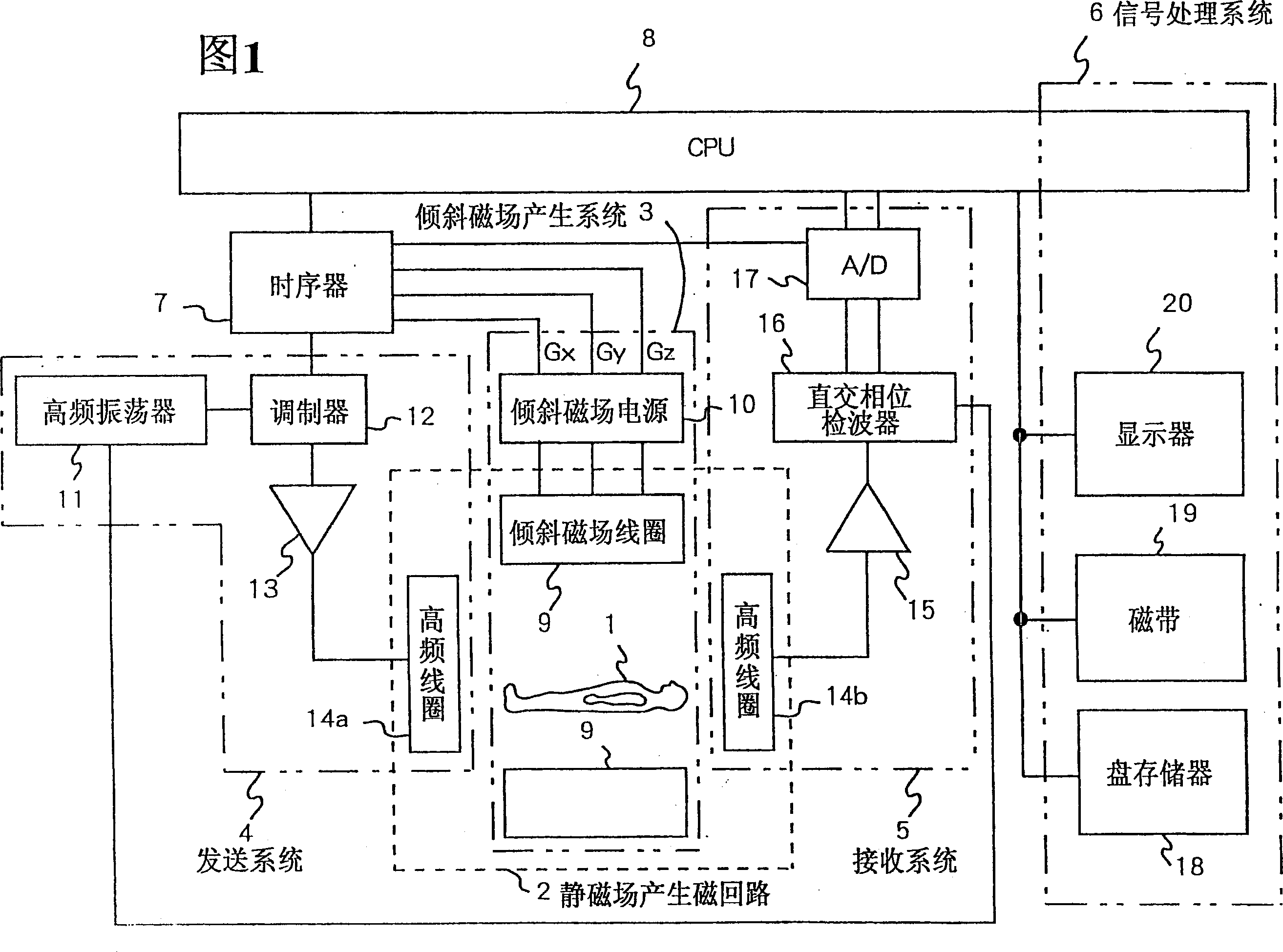
[0035] First, the overall configuration of the magnetic resonance imaging apparatus in this embodiment will be described with reference to FIG. 1 . The magnetic resonance imaging device of the present embodiment utilizes the magnetic resonance (NMR) phenomenon to obtain a tomographic image of the subject 1, so a magnetic circuit 2 and a central processing unit (hereinafter referred to as CPU) are generated by a static magnetic field with a sufficiently large opening required. 8. A sequencer 7, a sending system 4, a gradient magnetic field generating system 3, a receiving system 5, and a signal processing system 6 are formed.

[0036] The above-mentioned static magnetic field generating magnetic circuit 2 generates a uniform magnetic flux around the above-mentioned object 1 in the direction of the axis of the object to be detected or in a direction perpen...


PUM


Abstract

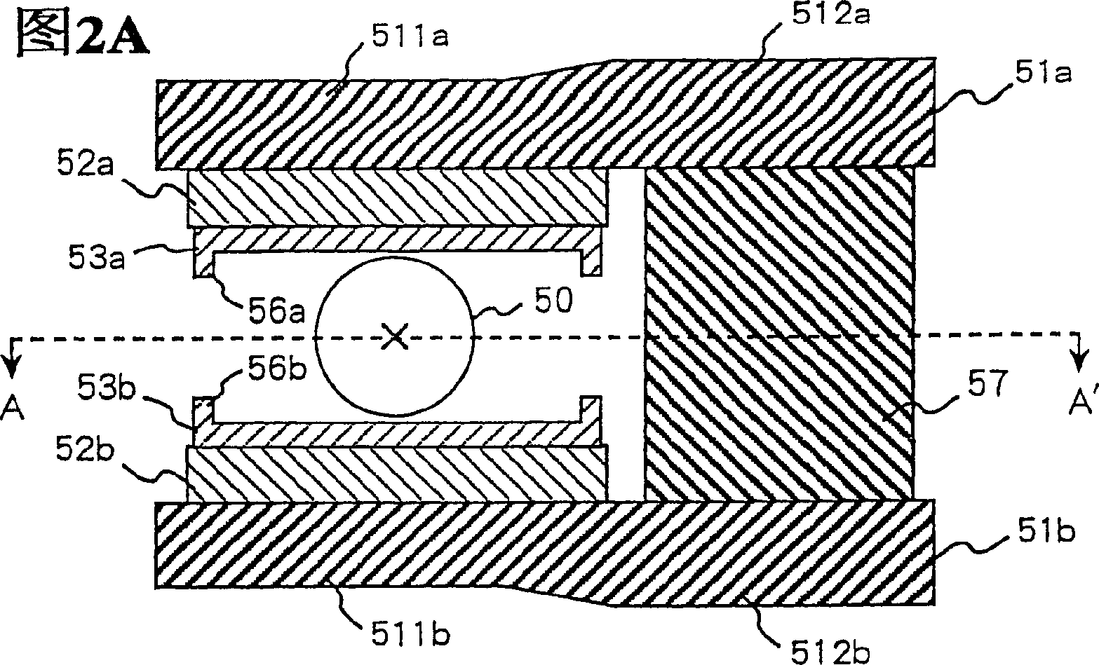
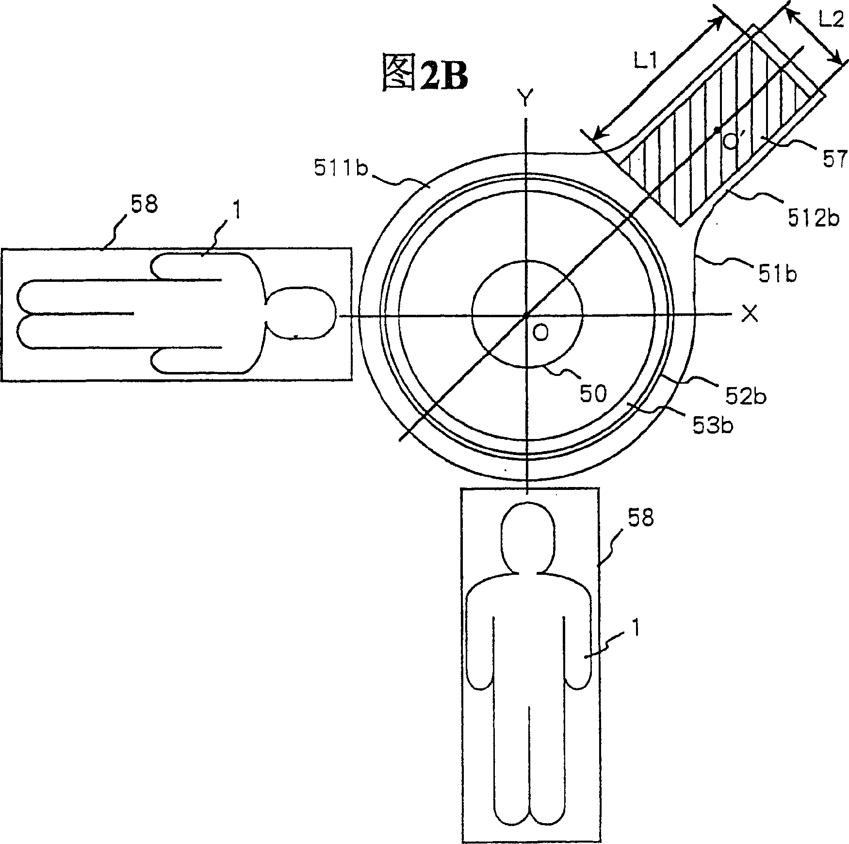
A magnetic resonance imaging apparatus has only one column supporting vertically opposed magnet devices of the apparatus, the periphery of the body of a yoke covering the magnet devices is shaped in an arc to improve its openness and the accessibility of the operator to the subject.

Description

[0001] This application is a divisional application of the application with the application number 01810225.5 and the title of the invention "Magnetic Resonance Imaging Apparatus" filed on December 4, 2002. technical field [0002] The present invention relates to an optimal static magnetic field generating device suitable for IVR of a magnetic resonance imaging device. Background technique [0003] A magnetic resonance imaging apparatus obtains a tomographic image of an inspection site of a subject by utilizing the nuclear magnetic resonance (NMR) phenomenon. In order to utilize this NMR phenomenon, it is necessary to place the object to be detected in a static magnetic field, and a magnet is used to generate the static magnetic field. There are permanent magnets, superconducting magnets, and permanent magnets in this magnet, and it can be divided into horizontal magnetic field type and vertical magnetic field type according to the direction of the magnetic field. [0004]...

Claims


Application Information

Patent Timeline
Patent Type & Authority Applications(China)
IPC IPC(8): A61B5/055G01R33/38G01R33/3815G01R33/383
CPCG01R33/3806G01R33/3815G01R33/383
Inventor 吉野仁志前田常雄
Owner HITACHI MEDICAL CORP
Learn More