Modularized joint of space manipulator

A technology of modular joints and space manipulators, applied in the direction of manipulators, manufacturing tools, joints, etc., can solve the problems of poor safety reliability and complex structure of space manipulator joints, and achieve the effects of shortening the development cycle, reliable transmission and simple structure

Inactive Publication Date: 2006-07-26
HARBIN INST OF TECH
View PDF0 Cites 53 Cited by
  • Summary
  • Abstract
  • Description
  • Claims
  • Application Information

AI Technical Summary

Problems solved by technology

[0003] The purpose of the present invention is to provide a space with high intelligence, high integration, high reliability, compact structure and adaptability to the space environment in order to solve the problem of poor safety reliability and complex structure of the joints of space manipulators in the field of space robots. Robotic Arm Modular Joints

Method used


Image

  • Modularized joint of space manipulator
  • Modularized joint of space manipulator
  • Modularized joint of space manipulator

Examples


specific Embodiment approach 1

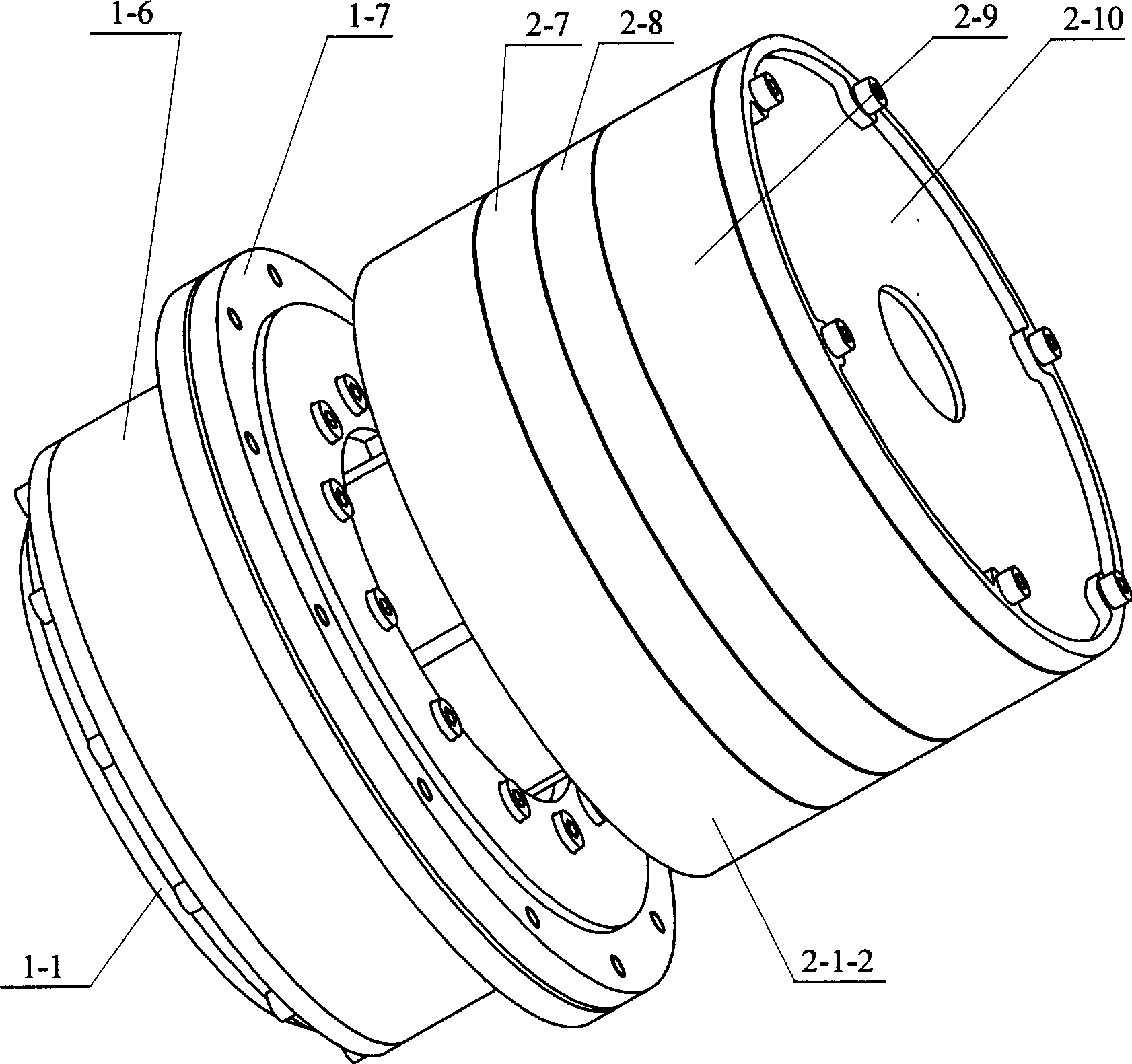
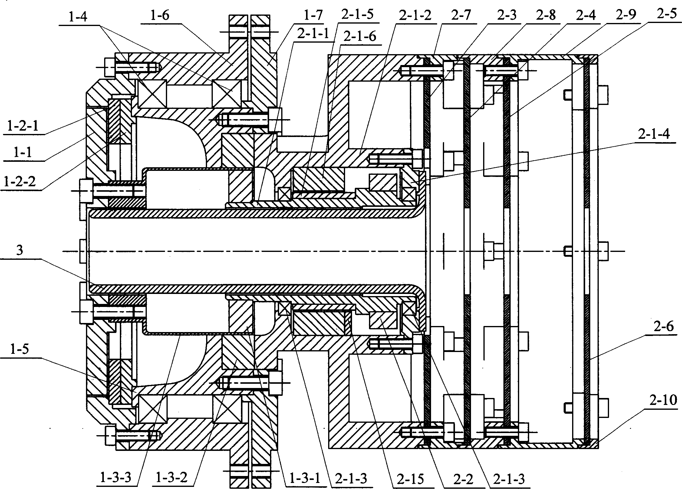
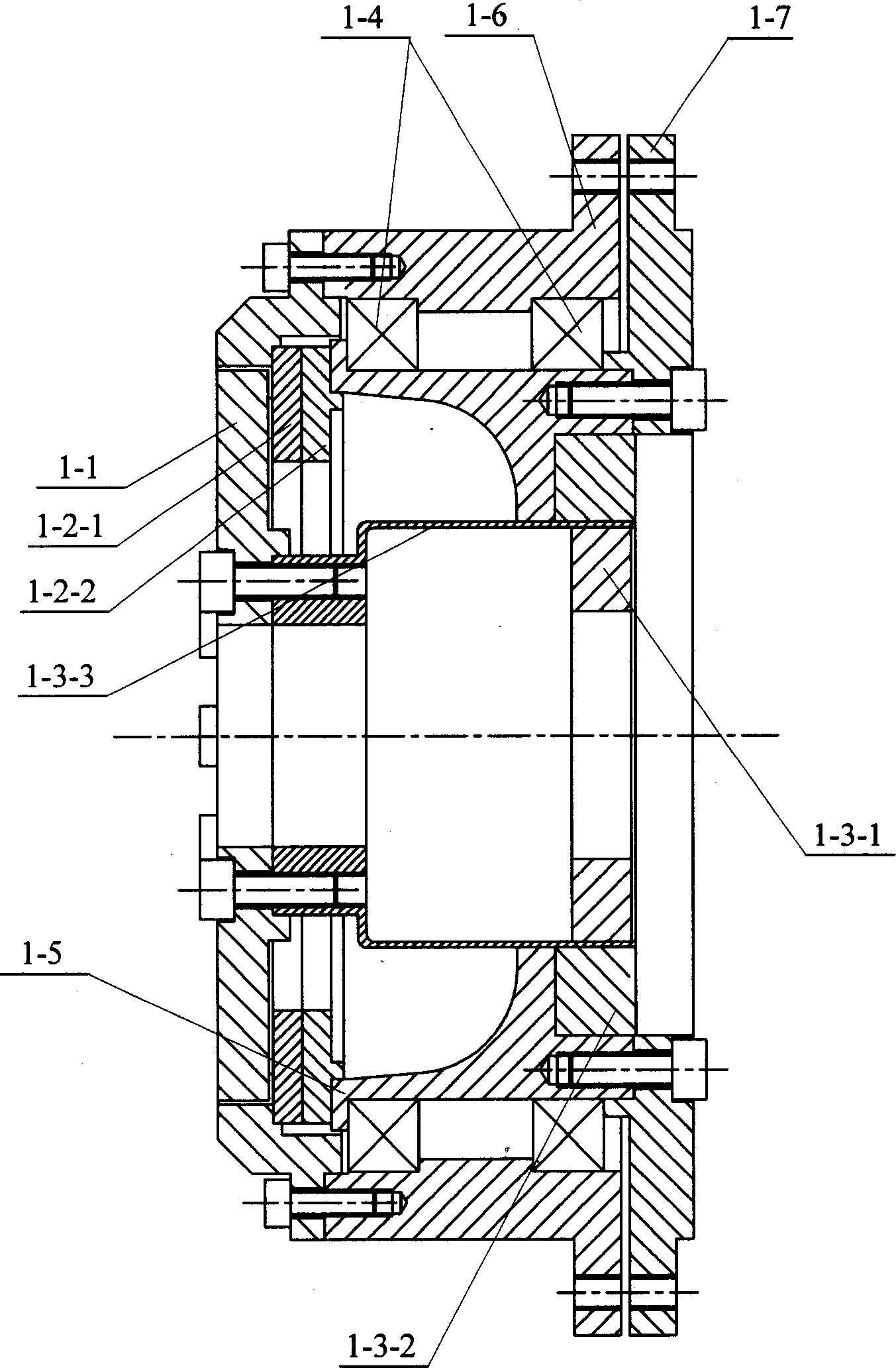
[0007] Specific implementation mode one: combine Figure 1~4 Describe this embodiment, this embodiment is made up of joint mechanism, motor device and sleeve 3; Described joint mechanism is made up of torque sensor 1-1, position sensor, harmonic reducer, bearing 1-4, bearing inner ring seat 1 -5. Bearing outer ring seat 1-6 and connecting flange 1-7, the harmonic reducer is composed of wave generator 1-3-1, rigid wheel 1-3-2 and flexible wheel 1-3- 3, the motor device is composed of a DC brushless motor, a magnetic encoder 2-2, a drive circuit board 2-3, a control circuit board 2-4, a power supply circuit board 2-5, an interface circuit board 2-6, a A bracket 2-7, a second bracket 2-8, a third bracket 2-9 and a pressure ring 2-10, the brushless DC motor is composed of a motor shaft 2-1-1, a motor housing 2-1-2 , motor bearing 2-1-3, end cover 2-1-4, motor rotor 2-1-5 and motor stator 2-1-6; motor casing 2-1-2 is fixed with motor stator 2-1 -6, the motor rotor 2-1-5 is housed...

specific Embodiment approach 2

[0009] Specific implementation mode two: combination figure 2 Describe this embodiment, the difference between this embodiment and the specific embodiment one is: the motor device of this embodiment is also added with a digital Hall sensor 2-15; -1-2 and fixedly connected with the motor stator 2-1-6. Redundant measurement of the motor position: it can be measured separately through the digital Hall sensor 2-15 and the magnetic encoder 2-2, which can improve the reliability of the system. If one is broken, the other can work independently.

specific Embodiment approach 3

[0010] Specific implementation mode three: combination Figure 7-9Describe this embodiment, the torque sensor 1-1 of this embodiment is made up of torque input disc 1-1-1, torque output disc 1-1-2, strain beam, strain gage, four sensor protection beams and four protection pads Composition; the strain beam is composed of a first strain beam 1-1-3-1, a second strain beam 1-1-3-2 and a third strain beam 1-1 uniformly distributed along the circumference of the moment input disc 1-1-1 -3-3 and the fourth strain beam 1-1-3-4, the first strain beam 1-1-3-1, the second strain beam 1-1-3-2, the third strain beam 1-1- 3-3 and the two ends of the fourth strain beam 1-1-3-4 are respectively made into one body with the torque input disc 1-1-1 and the torque output disc 1-1-2, and the strain gauges are respectively pasted on the The first strain gauge 1-1-4-1 and the second strain gauge 1-1-4-2 on the first strain beam 1-1-3-1, pasted on the second strain beam 1-1-3-2 The third strain gau...


PUM


Abstract

The invention relates the spacing robot arm joint. The invention aims to the problem of bad safe reliability of spacing mechanical arm joint and complicated structure. The wave generating machine (1-3-1) is fixed in direct current brushless motor, soft wheel (1-3-3) is installed on wave generating machine (1-3-1), hand wheel (1-3-2) is installed on soft wheel (1-3-3), bearing inner ring seat (1-5) is installed on hand wheel (1-3-2), hand wheel (1-3-2) is connected with direct current brushless motor, soft wheel (1-3-3) is connected with torque pick-up (1-1), address sensor is installed between torque pick-up (1-1) and bearing inner ring seat (1-5), torque pick-up (1-1) is connected with bearing out ring seat (1-6), bearing (1-4) is installed between bearing out ring seat (1-6) and bearing inner ring seat (1-5), magnetic code device (2-2) is installed on direct current brushless motor, sleeve (3) is installed in direct current brushless motor, and drive board (2-3), control board (2-4), power board (2-5) and interface board (2-6) are connected with each other by frame, direct current brushless motor and compression ring (2-10). The invention possesses the high intelligentize degree and integration degree.

Description

technical field [0001] The invention relates to a space manipulator joint. Background technique [0002] With the rapid development of space science and technology, the development and utilization of energy will expand to space in the future. But many space activities are inseparable from space robots, such as the construction and maintenance of space stations, and the release and recovery of satellites. Since the concept of space robot was proposed, until now, the space robot arm Canadarm2 of the Canadian Space Agency (CSA) is the only space robot arm used in actual work. ETS-VII, launched by the Nippon Space Development Agency (NSADA), is the world's first satellite equipped with a robotic arm. NASA has developed an assistant for astronauts called "Robonaut." Robonaut is a humanoid robot proposed as a tool that is efficient, energy-saving and can help people perform a large number of space activities. The German Aerospace Center (DLR) has developed three generations of...

Claims


Application Information

Patent Timeline
Patent Type & Authority Applications(China)
IPC IPC(8): B25J17/00
Inventor 刘宏史士财高晓辉金明河谢宗武
Owner HARBIN INST OF TECH
Why Eureka
Try Eureka