

Method for removing static on substrate, apparatus and base thereof
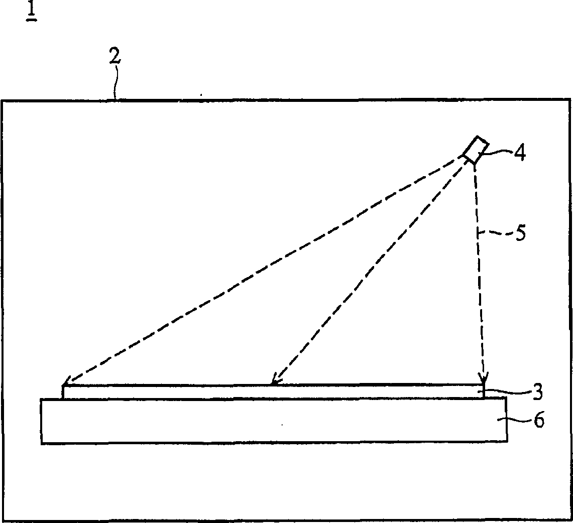
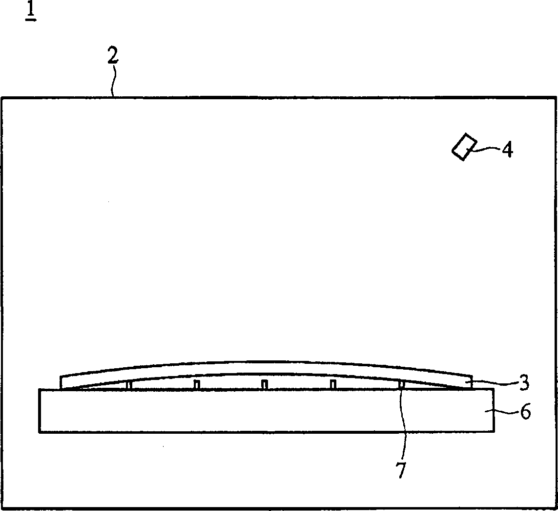
A substrate and base technology, which is applied in the manufacture of circuits, electrical components, semiconductor/solid-state devices, etc., can solve the problems of bending of the glass substrate 3, uneven force on the glass substrate 3, fragmentation, etc., so as to avoid fragmentation and prevent stress. The effect of unevenness and elimination of static electricity
- Summary
- Abstract
- Description
- Claims
- Application Information
AI Technical Summary
Problems solved by technology
Method used
Image

Examples
no. 1 example
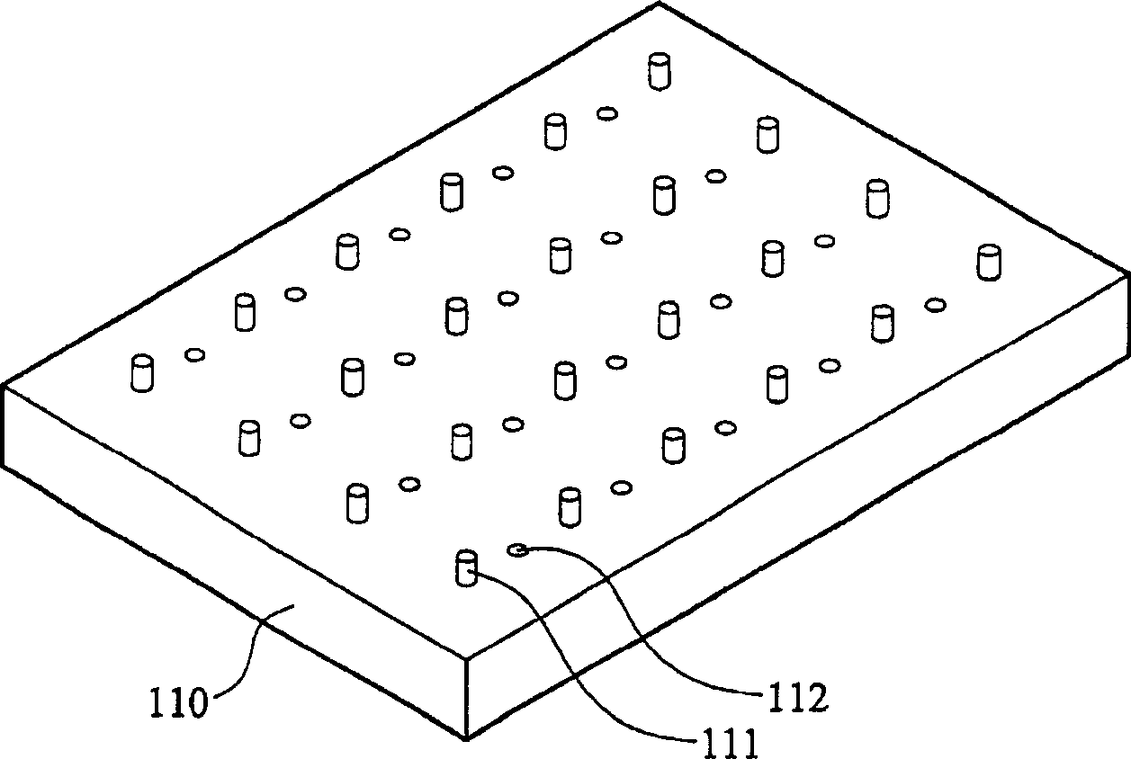
[0028] Figure 2a A base 110 of an exposure tool according to a first embodiment of the present invention is shown. In this embodiment, a plurality of support structures (support columns) 111 and a plurality of openings 112 are disposed on the base 110 . The support structures 111 are arranged in a matrix, and can be placed at the first position (such as Figure 2a the location shown) and the second location ( Figure 2b displayed locations). Such as Figure 3a As shown, when the supporting structure 111 is in the second position, the substrate 3 is placed on the base 110 . After the substrate 3 is exposed, as Figure 3b As shown, the support structure 111 rises to the first position to lift the substrate 3 . refer to Figure 3c , the exposure machine 100 includes a cavity 120 , a base 110 and an ion gas generator 114 . The base 110 is disposed in the cavity 120 . The ion gas generator 114 is disposed in the base 110 . A pipeline 113 is provided in the base 110 to co...
no. 2 example
[0032] Figure 4a An exposure machine 100' according to a second embodiment of the present invention is shown. In this embodiment, the exposure machine 100' further includes a plurality of protruding columns (nozzles) 116 disposed on the upper surface of the base 110. When the ion gas 115 is blown, the ion gas 115 can be ejected from the protruding pillars 116 and contact the upper surface of the substrate 3 from above the substrate 3 , thereby eliminating static electricity on the upper surface of the substrate 3 . In the second embodiment of the present invention, it is not necessary to use the X-rays generated by the X-ray generator to eliminate the static electricity on the upper surface of the substrate.
[0033] refer to Figure 4b , when the substrate 3 is placed on the base 110 , the protruding pillars 116 can be disposed on the periphery of the substrate 3 to surround the substrate 3 so as to uniformly and fully provide the ion gas to the substrate 3 .
[0034] In ...
no. 3 example
[0036] Figure 5 An exposure machine 200 of a third embodiment of the present invention is shown. In this embodiment, a vent 117 is provided at the center of the supporting structure 111 , and the vent 117 communicates with the pipeline 113 . When the static charge on the lower surface of the substrate 3 is to be eliminated, the ion gas generator 114 generates the ion gas 115 , and contacts the lower surface of the substrate 3 through the pipeline 113 and the vent 117 .
[0037] The exposure machine 200 of the third embodiment can be equipped with a plurality of openings in the first embodiment, so as to increase the contact area between the ion gas and the lower surface of the substrate, and enhance the electrostatic charge elimination effect on the lower surface of the substrate. Alternatively, the exposure machine 200 of the third embodiment can also be equipped with the X-ray generator in the first embodiment to eliminate static charges on the upper surface of the substra...
PUM
 Abstract
Description
Claims
Application Information