Intake air volume controller of internal combustion engine

A technology of control system and intake air volume, applied in general control system, control/regulation system, electrical control, etc., can solve the problem of inability to correct the change of cylinder intake air volume, deterioration of combustion state, deterioration of drivability and exhaust emission characteristics, etc. question

Inactive Publication Date: 2006-08-09
HONDA MOTOR CO LTD
View PDF0 Cites 6 Cited by
  • Summary
  • Abstract
  • Description
  • Claims
  • Application Information

AI Technical Summary

Problems solved by technology

Therefore, there is a problem that it is not possible to correct for variations in the intake air amount between cylinders
Therefore, in the engine speed control, in a very low load region (eg, idle speed region), rotation variation can be suppressed

Method used


Image

  • Intake air volume controller of internal combustion engine
  • Intake air volume controller of internal combustion engine
  • Intake air volume controller of internal combustion engine

Examples


Example Embodiment

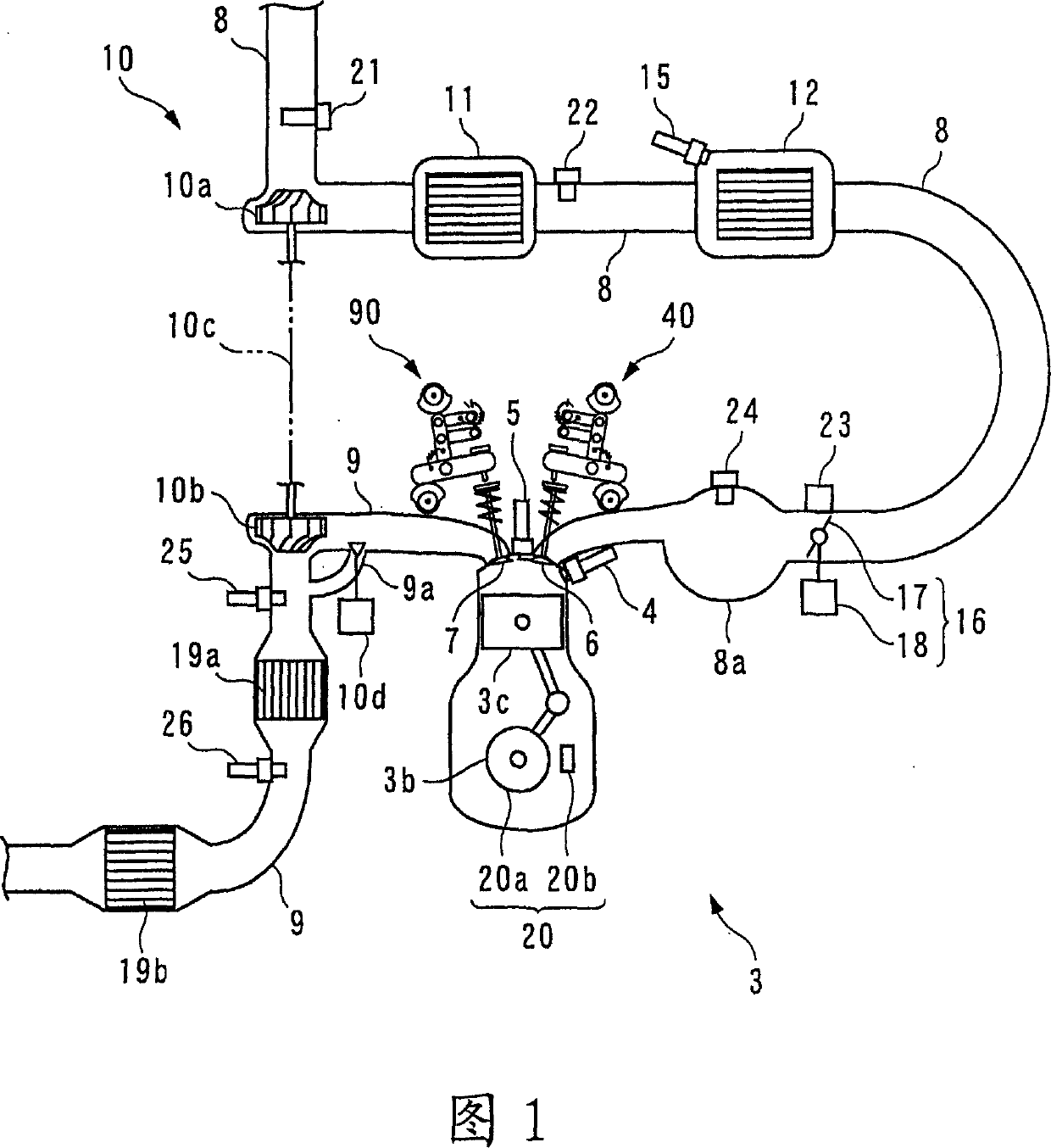
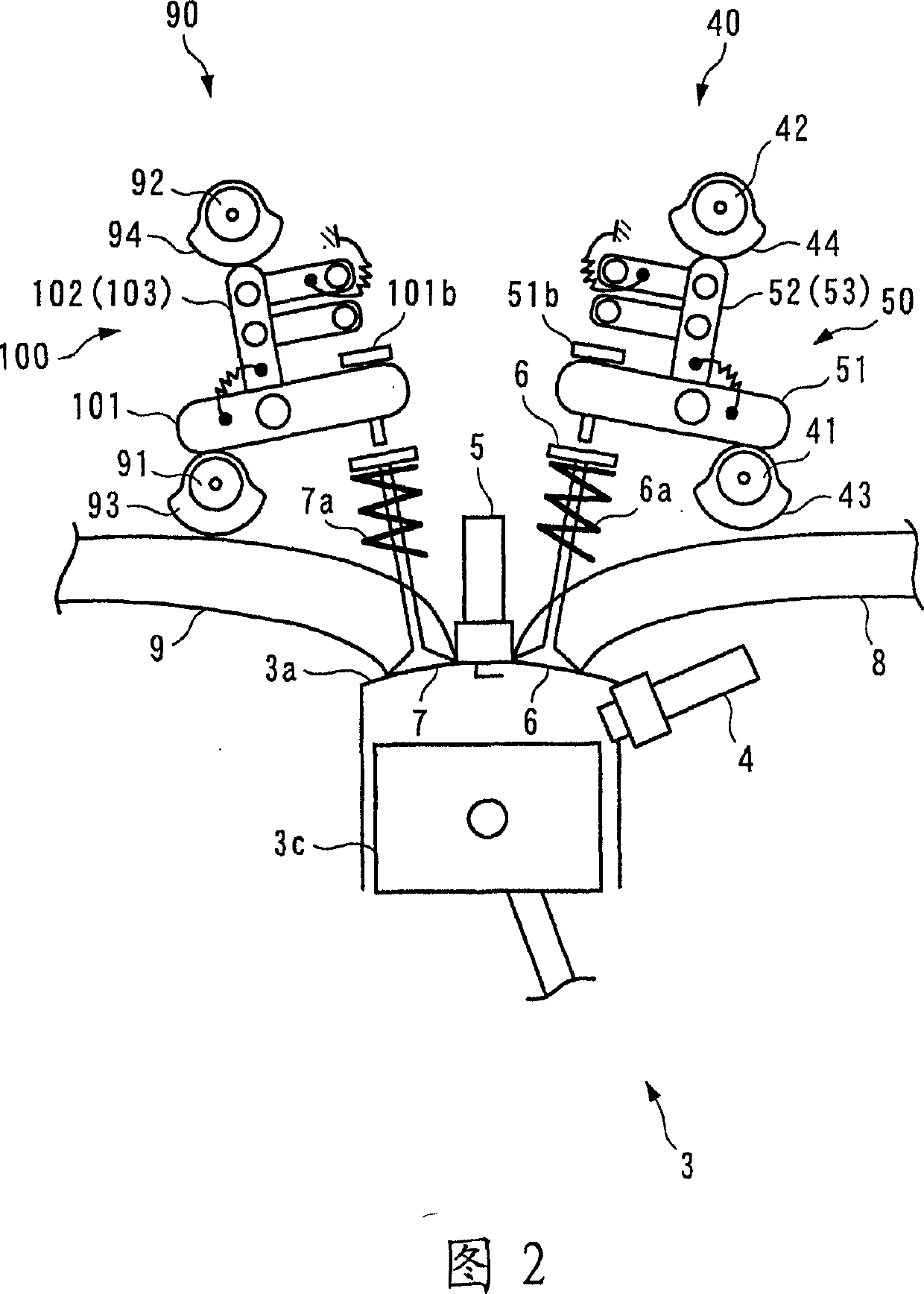
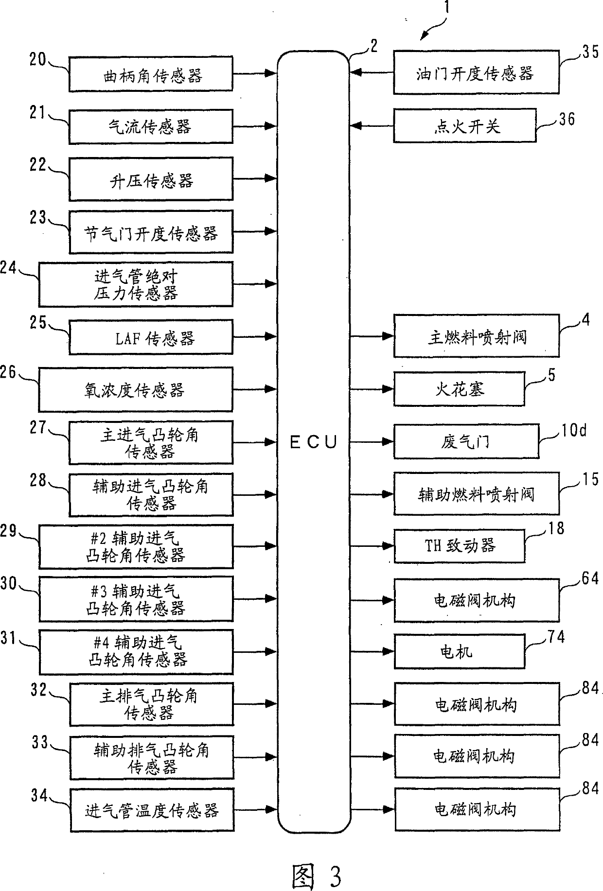
[0089] Hereinafter, an intake air amount control system (hereinafter simply referred to as "control system") according to an embodiment of the present invention will be described with reference to the accompanying drawings. Referring first to FIGS. 1 and 2, the structure of an internal combustion engine 3 (hereinafter simply referred to as "engine 3") to which the control system 1 according to this embodiment is applied is schematically shown. FIG. 3 schematically shows the structure of the control system 1. As shown in FIG. 3, the control system 1 includes an ECU 2. As described below, the ECU 2 executes various control processes based on the operating state of the engine 3, including intake valve control processes for controlling the amount of intake air.

[0090] The engine 3 is an in-line four-cylinder gasoline engine mounted on a car (not shown), and has first cylinder #1 to fourth cylinder #4 (a plurality of cylinders) (see FIG. 5). In addition, the engine 3 includes a main ...


PUM


Abstract

An intake air amount control system for an internal combustion engine, which controls respective amounts of intake air drawn into four cylinders #1 to #4, independently of each other, by variable inter-intake cam phase mechanisms 80, identifies intake air amount variation coefficients ¦#i, based on a model [equation (43)] defining a relationship between an estimated value Gth_est of a TH passing intake air amount and a plurality of simulation values Gcyl_OS#i, such that the estimated value Gth_est becomes equal to the TH passing intake air amount, calculates a target inter-intake cam phase ¸ssi#i_cmd, on a cylinder-by-cylinder basis, according to the identified intake air amount variation coefficients ¦#i (step 81), and calculates control input DUTY_ssi#2 to #4 to the variable inter-intake cam phase mechanisms 80 according to the target inter-intake cam phases ¸ssi#i_cmd (step 75).

Description

technical field [0001] The present invention relates to an intake air quantity control system for an internal combustion engine, which controls the respective intake air quantities drawn into a plurality of cylinders. Background technique [0002] Conventionally, as an intake air amount control system for an internal combustion engine, for example, an intake air amount control system described in Patent Document 1 is known. The engine is of a four-cylinder type, and includes: a solenoid valve mechanism provided for each cylinder for changing a valve closing timing relative to a valve opening timing of each cylinder; and a throttle mechanism. As described below, in this intake air amount control system, in order to control the idling speed, the valve closing timing of each intake valve is controlled by a solenoid valve mechanism, thereby controlling the intake air amount. More specifically, the target intake air amount for feedforward control is calculated from the target en...

Claims


Application Information

Patent Timeline
IPC IPC(8): F02D13/02F01L1/34F02D41/04F02D45/00G05B13/02F02D43/00F01L13/00F02B27/02F02D41/00F02D41/14F02D41/18F02D41/34G05B13/04
CPCF01L13/0047F02D2041/001F01L1/08F02D41/1401F02D41/0085F02D41/18Y02T10/146F02D13/0207F01L1/18Y02T10/42Y02T10/18G05B13/04F02B27/0263F01L1/181F02D2200/0402F02D2041/1416F02D41/0002F01L2800/00F02B27/02F02D2041/1437Y02T10/12Y02T10/40
Inventor 安井裕司米川明之
Owner HONDA MOTOR CO LTD
Why Eureka
Try Eureka